Systems, Devices and Methods for Cardiopulmonary Treatment and Procedures

a cardiopulmonary and systemic technology, applied in the field of systems, devices and procedures for cardiopulmonary treatment and procedures, can solve the problems of pulmonary, renal and cerebral dysfunction, pulmonary and renal failure, and the volume of extra fluid to be delivered to the patient, so as to reduce the shear force and reduce the hard snapping of the membrane

Active Publication Date: 2009-04-16
DEKA PROD LLP
View PDF99 Cites 203 Cited by
  • Summary
  • Abstract
  • Description
  • Claims
  • Application Information

AI Technical Summary

Benefits of technology

[0013]Additionally, the inlet of the pumps can further direct flow through the rigid chamber wall into the pumping chamber in a direction that provides low-shear flow into the pumping chamber; and the outlet of the pumps can further direct flow through the rigid chamber wall out of the pumping chamber in a direction that provides low-shear flow out of the pumping chamber.
[0014]In a particular embodiment, the reciprocating positive-displacement pump uses a flexible membrane made from a material that reduces hard snapping of the membrane as the membrane reciprocates from one position in the pump chamber to the other. The central portion of the membrane may include protuberances that space the central portion away from the rigid chamber wall when the membrane is in a minimum-pumping-chamber-volume position. Such protuberances prevent blood from being trapped between a portion of the membrane and the wall, and reduce the shear forces exerted on the blood being pumped. In another embodiment, the rigid inner wall of the pumping chamber can have a channel or recess fluidly connecting the inlet fluid path with the outlet fluid path of the pump, the channel or recess at least partially inaccessible to contact with the flexible membrane when it is pressed against the rigid chamber wall of the pumping chamber.

Problems solved by technology

The CPB circuit must be purged of air and primed with a saline solution prior to commencing bypass, which causes a substantial volume of extra fluid to be delivered to the patient.
Some of these complications include anemia and edema, as well as inflammatory responses caused by the exposure of blood to plastic components, all of which can lead to pulmonary, renal and cerebral dysfunction.
These complications can be exacerbated by the damage caused to the cellular elements of the blood (such as red blood cells) by the pumps used in a typical CPB circuit.
Any of these types of pumps can create high shear forces on the cellular elements of the blood, leading to hemolysis and platelet activation, which can have several detrimental effects on the patient.
Furthermore, microemboli of air, fat, platelet aggregates, thrombi, atheromatous plaque fragments and other debris can enter the patient's circulatory system, also leading to ischemic and inflammatory events in various organs.
However, reducing the priming volume alone does not necessarily ameliorate other major problems associated with CPB, including, for example, hemolysis and the propagation of microemboli.
The risk of microembolization may be increased if arterial-line filters are eliminated; and there may be increased risk of air embolization with the use of vacuum-assisted venous drainage, or if venous reservoirs are bypassed.
Concerns have also been raised about the potential detrimental effects of continuous flow vs. pulsatile flow in both CPB and in other forms of assisted circulation.
Absence of pulsatile blood flow could lead to a loss of baroreceptor-mediated control of blood circulation in the patient, and result in a decrease in regional blood flow and oxygen delivery.
However, most of these attempts require the addition of devices to the CPB circuit, increasing their complexity, the priming volume and the opportunity for additional shear stress to be applied to the cellular elements of the blood.

Method used


Image

  • Systems, Devices and Methods for Cardiopulmonary Treatment and Procedures
  • Systems, Devices and Methods for Cardiopulmonary Treatment and Procedures
  • Systems, Devices and Methods for Cardiopulmonary Treatment and Procedures

Examples


Embodiment Construction

[0101]Definitions. As used in this description and the accompanying claims, the following terms shall have the meanings indicated, unless the context otherwise requires:

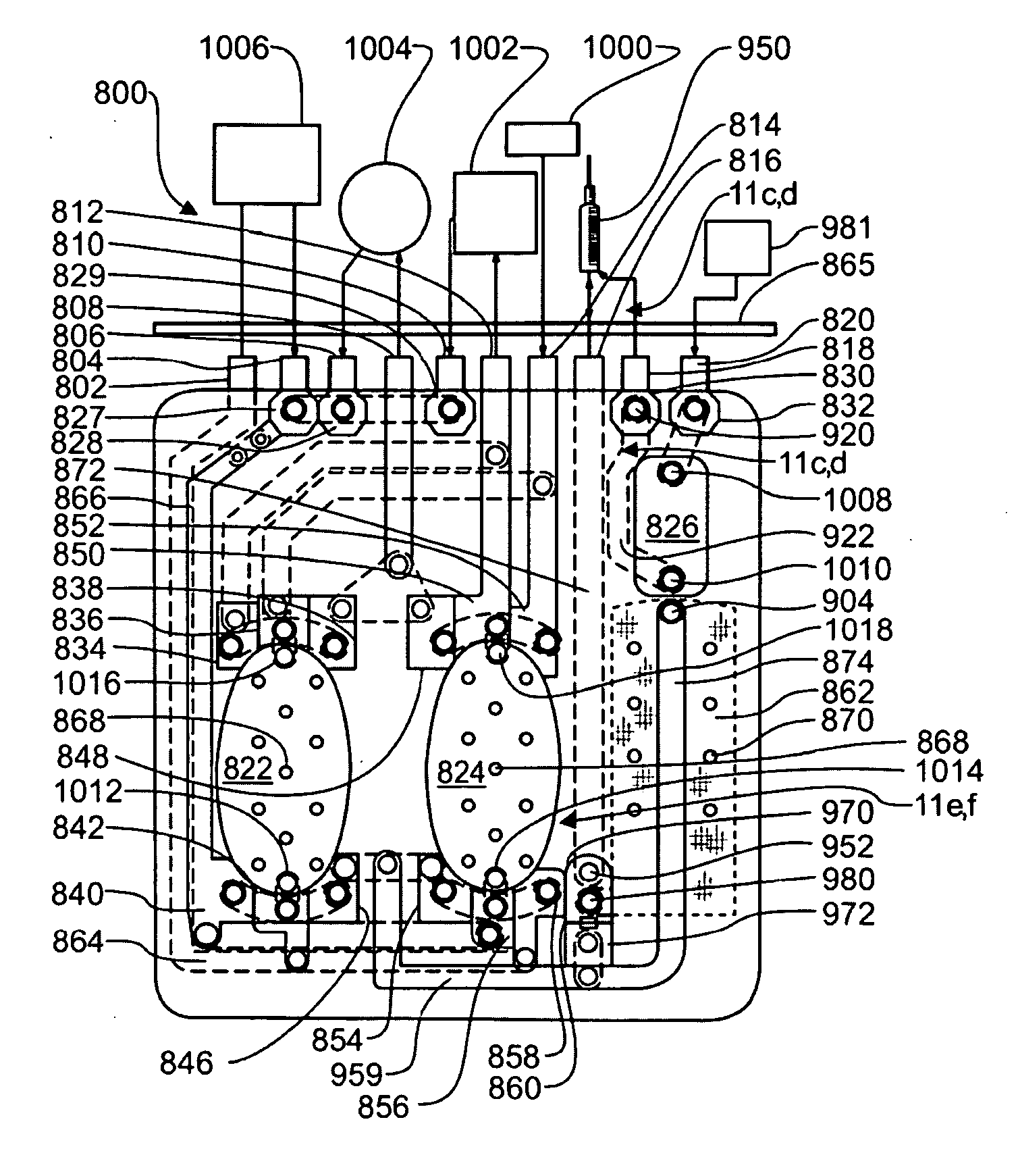
[0102]“Spheroid” means any three-dimensional shape that generally corresponds to a oval rotated about one of its principal axes, major or minor, and includes three-dimensional egg shapes, oblate and prolate spheroids, spheres, and substantially equivalent shapes.

[0103]“Hemispheroid” means any three-dimensional shape that generally corresponds to approximately half a spheroid.

[0104]“Spherical” means generally spherical.

[0105]“Hemispherical” means generally hemispherical.

[0106]“Dithering” a valve means rapidly opening and closing the valve.

[0107]“Pneumatic” means using air or other gas to move a flexible membrane or other member.

[0108]“Substantially tangential” means at an angle less than 75° to a tangent, or in the case of a flat wall, at an angle of less than 75° to the wall.

[0109]“Fluid” shall mean a substance, a li...


PUM


Abstract

A cardiopulmonary bypass system utilizing membrane-based reciprocating positive displacement blood pumps (“pod pumps”). In one aspect, the pod pumps are constructed to provide reduced shear forces on the blood being pumped. In another aspect blood flow through the pod pumps can be controlled by a controller using information from pressure sensors in the control chamber of the pod pumps. In another aspect, the pod pumps are included on a disposable unit that can be received and held by a receptacle means on a base unit, the base unit also providing pressurized control fluid to the pod pumps on the disposable unit through the receptacle means.

Description

CROSS REFERENCE TO RELATED APPLICATIONS[0001]The present application is a Non-provisional Application which claims priority from U.S. Provisional Patent Application Ser. No. 60 / 998,881, filed Oct. 12, 2007.TECHNICAL FIELD[0002]The present inventions relate to systems, devices and methods of cardiopulmonary treatment and procedures. Additionally, the present invention relates to pumps and other flow-control systems and methods, and in particular to pumps that impart low shear forces and turbulence on the fluid being pumped for systems, devices and methods of cardiopulmonary treatment and procedures. Flow control systems in the present invention can include devices for sensing pressures within pumps, determining pumping volumes and flow rates, and for altering fluid flow paths among several pumps using actively controlled valves interposed in fluid flow paths. Additionally, the present invention relates to heat exchanger systems for systems, devices and methods of cardiopulmonary trea...

Claims


Application Information

Patent Timeline
Patent Type & Authority Applications(United States)
IPC IPC(8): A61M1/16A61M1/32
CPCA61M1/106A61M2205/127A61M1/3666A61M1/3621A61M1/3667Y10T137/86035A61M60/113A61M60/43G01F22/02A61M60/554A61M60/427A61M60/531A61M1/362227A61M1/36224A61M1/362266A61M1/362265A61M1/36223A61M1/36226A61M1/362264A61M1/36225
Inventor DEMERS, JASON A.GRAY, LARRY B.DALE, JAMES D.PERRY, N. CHRISTOPHERALTOBELLI, DAVID E.
Owner DEKA PROD LLP
Why Eureka
Try Eureka