Thread tension adjustment mechanism of sewing machine

A tension adjustment and sewing machine technology, which is applied to sewing machine components, tension devices, sewing equipment, etc., can solve the problems of inconvenience in assembly, easy to scratch threads, increase in manufacturing cost, etc., so as to improve the convenience of assembly and avoid vibration loosening. , The effect of saving assembly components

Active Publication Date: 2013-12-04
顾飞龙
View PDF5 Cites 1 Cited by
  • Summary
  • Abstract
  • Description
  • Claims
  • Application Information

AI Technical Summary

Problems solved by technology

However, according to this embodiment, it is often found that when the user stretches the groove of the screw rod, the direction of the applied force is different, so that the screw rod is unevenly deformed, and the roundness is damaged (such as Figure 7 As shown), it cannot align with the screw hole of the knob, so that when the screw is screwed to the screw hole of the knob, the sharp angle formed by the deformed metal screw is easy to scratch the thread in the screw hole of the plastic knob, and the reverse will happen over time. Circumstances that result in the knob not being tightly screwed to the screw
[0006] Furthermore, if it is found that the knob and the screw will gradually loosen, in order to further increase the screw tightening force between the two, the user will open the groove on the screw again, and this vicious cycle will repeatedly open the groove. The screw is prone to breakage at the bottom of the groove, causing damage to the screw
[0007] In addition, the thread tension adjustment mechanism of the existing sewing machine must be processed on the screw rod to form a groove in the manufacture and assembly. , and then screw the knob, so the assembly of parts is cumbersome. In addition to the increase in manufacturing cost, the assembly is also quite time-consuming and inconvenient. In particular, the screw rod forming the groove lacks appropriate tools to be locked on the fixed plate or the body, and components such as positioning rings are bulky Small, easy to be lost during assembly, causing loss in manufacturing cost and inconvenient assembly

Method used


Image

  • Thread tension adjustment mechanism of sewing machine
  • Thread tension adjustment mechanism of sewing machine
  • Thread tension adjustment mechanism of sewing machine

Examples


Embodiment Construction

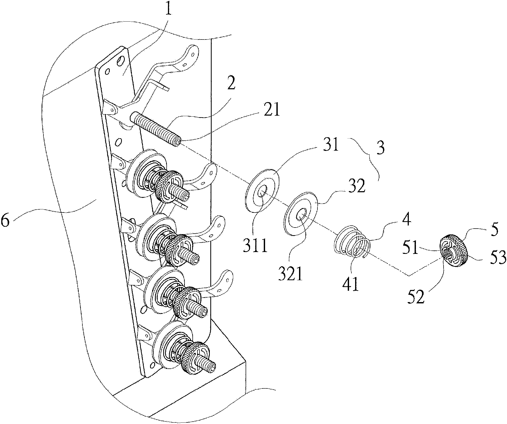
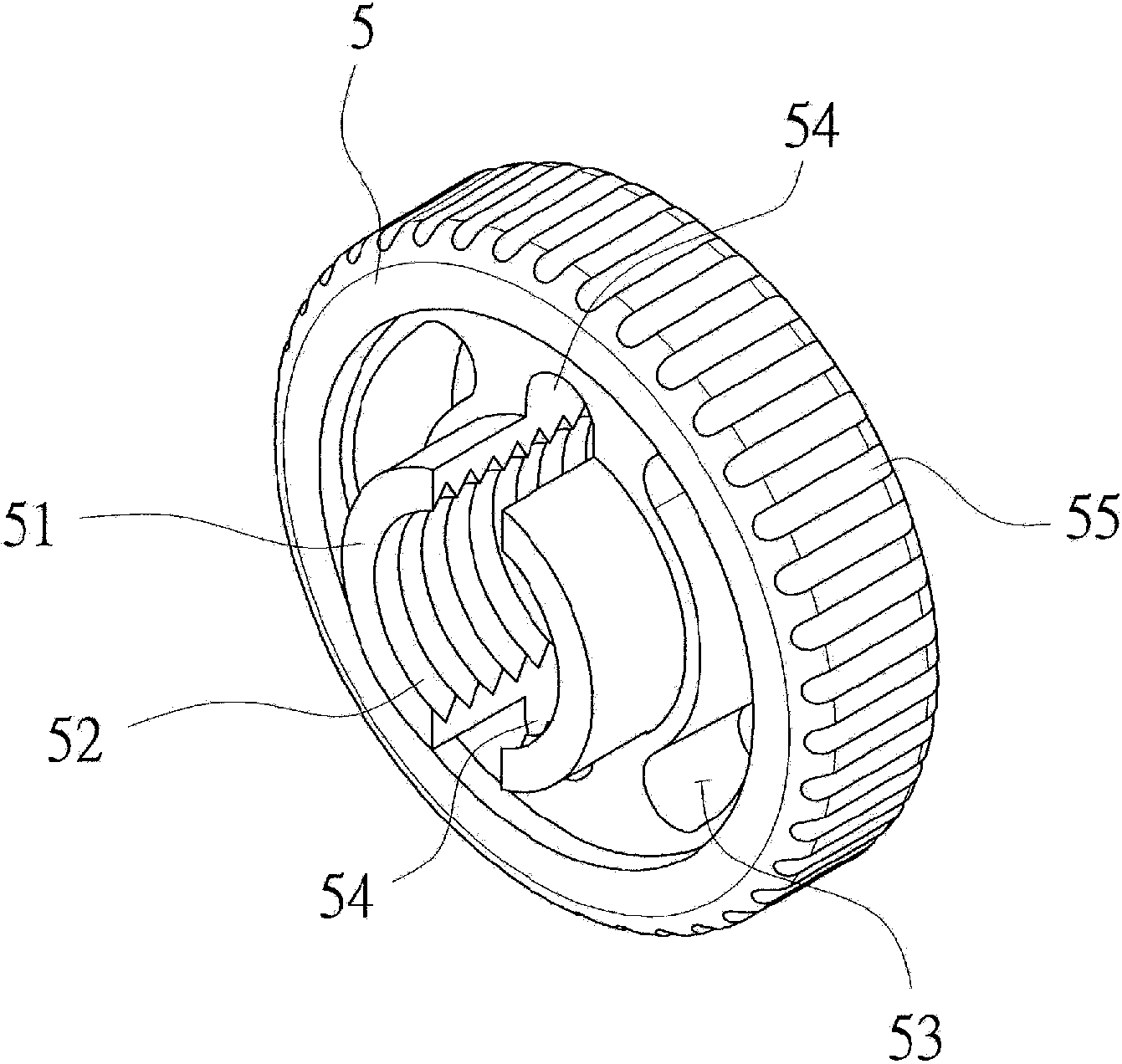
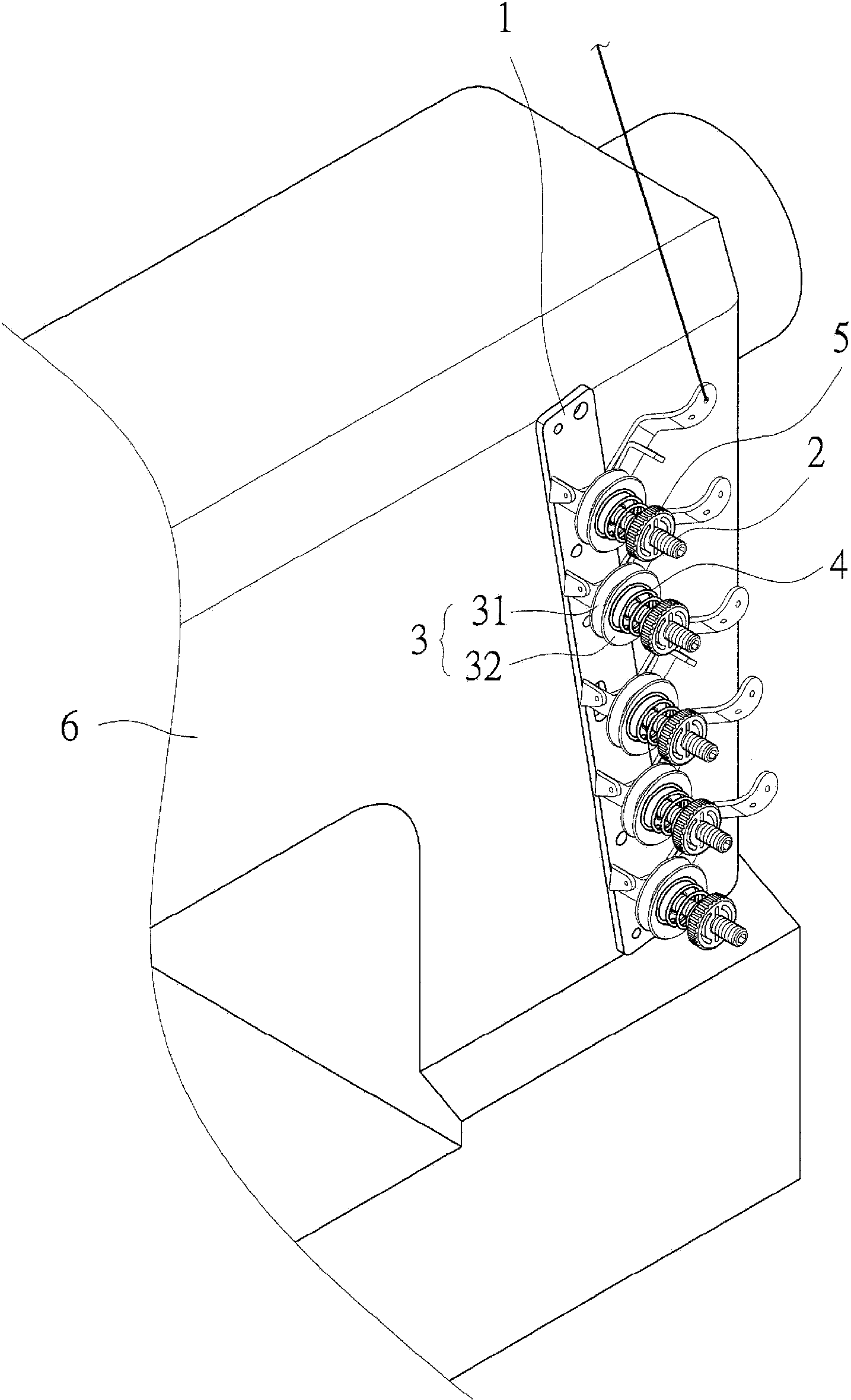
[0052] First, see figure 1 Shown is the suture tension adjustment mechanism of the sewing machine of the present invention, which is composed of a fixed plate 1, a screw rod 2, a thread tension piece 3, a spring 4 and a knob 5; wherein:

[0053] The fixing plate 1 is assembled with the body 6 of the sewing machine at an appropriate position;

[0054] The screw 2 is a solid rod body with no slots and threaded sections. A polygonal turning hole 21 is provided on the front end for the plate glove, and the other end is assembled to the screw hole of the machine body or the fixed plate 1. superior;

[0055] The clamping piece 3 includes a first clamping piece 31 and a second clamping piece 32, and the center of the first clamping piece 31 and the second clamping piece 32 are provided with through holes 311, 321 to be sleeved on the screw 2. Make the first clamping piece 31 and the second clamping piece 32 contact each other, and make the first clamping piece 31 stick to the fixe...


PUM


Abstract

The invention relates to a thread tension adjustment mechanism of a sewing machine. A screw is assembled on a sewing machine body, two thread champing pieces and a spring are connected with the screw in sequence in a sleeved manner to enable the two thread clamping pieces to be arranged between the spring and the machine body in a butted manner, a knob is arranged, a screw hole is formed in the center of the knob to be in screw joint with the screw and pressed on the spring in a butted manner, and a plurality of slots are formed in the periphery of the screw hole of the knob. Thereby, by the aid of the slots formed in the periphery of the screw hole of the knob, the knob screw hole with the diameter smaller than that of the screw can generate extension margin to benefit screw joint with the screw; when the knob is positioned to restore, the screw can be clamped tightly to be prevented from loosening due to vibration, and accordingly pressure on the spring is stabilized to keep adjustment statuses of a thread.

Description

technical field [0001] The invention relates to a sewing thread tension adjusting mechanism of a sewing machine, in particular to a sewing thread tension adjusting mechanism of a sewing machine capable of stabilizing the pressure of a spring on a thread tensioner to maintain a well-adjusted state of the sewing thread. Background technique [0002] With the advancement of industry, the sewing machine has been driven from manpower to electric drive, which has greatly increased the production capacity of the sewing machine. In addition, the accessories such as thread trimmer and clamping of the sewing machine have also been improved in many ways, making the sewing machine more convenient to operate. [0003] see Image 6 As shown, it is the sewing thread tension adjustment mechanism of the existing sewing machine. A fixing plate 72 is mainly assembled on the body 71 of the sewing machine 7, and several screw rods 73 are equidistantly arranged on the fixing plate 72, and the scre...

Claims


Application Information

Patent Timeline
Patent Type & Authority Applications(China)
IPC IPC(8): D05B47/04
Inventor 顾飞龙
Owner 顾飞龙
Why Eureka
Try Eureka