Eureka AIR delivers breakthrough ideas for toughest innovation challenges, trusted by R&D personnel around the world.

The electromagnetic valve

A solenoid valve and armature technology, applied in the field of solenoid valves, can solve problems such as corrosion

Active Publication Date: 2016-12-28
DENSO CORP
View PDF8 Cites 0 Cited by
  • Summary
  • Abstract
  • Description
  • Claims
  • Application Information

AI Technical Summary

Problems solved by technology

[0006] In this case, however, corrosion may occur by cavitation at, for example, the open end of the communication channel in the first armature chamber and / or the wall surface of the spring chamber

Method used


Image

  • The electromagnetic valve
  • The electromagnetic valve
  • The electromagnetic valve

Examples


no. 1 example )

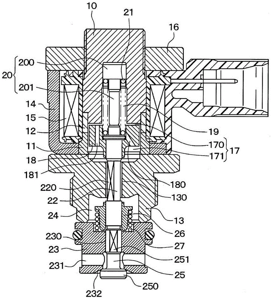
[0021] The solenoid valve of the present embodiment is used as a suction metering valve of a fuel injection device (also referred to as a fuel injection system). The fuel injection device supplies fuel to, for example, an internal combustion engine, more specifically a diesel engine. The fuel injection equipment has a pump and a (high pressure) common rail. The pump compresses fuel to high pressure and discharges the pressurized fuel toward the common rail. The common rail accumulates fuel under pressure. A suction metering valve regulates the flow of fuel supplied to the pump.

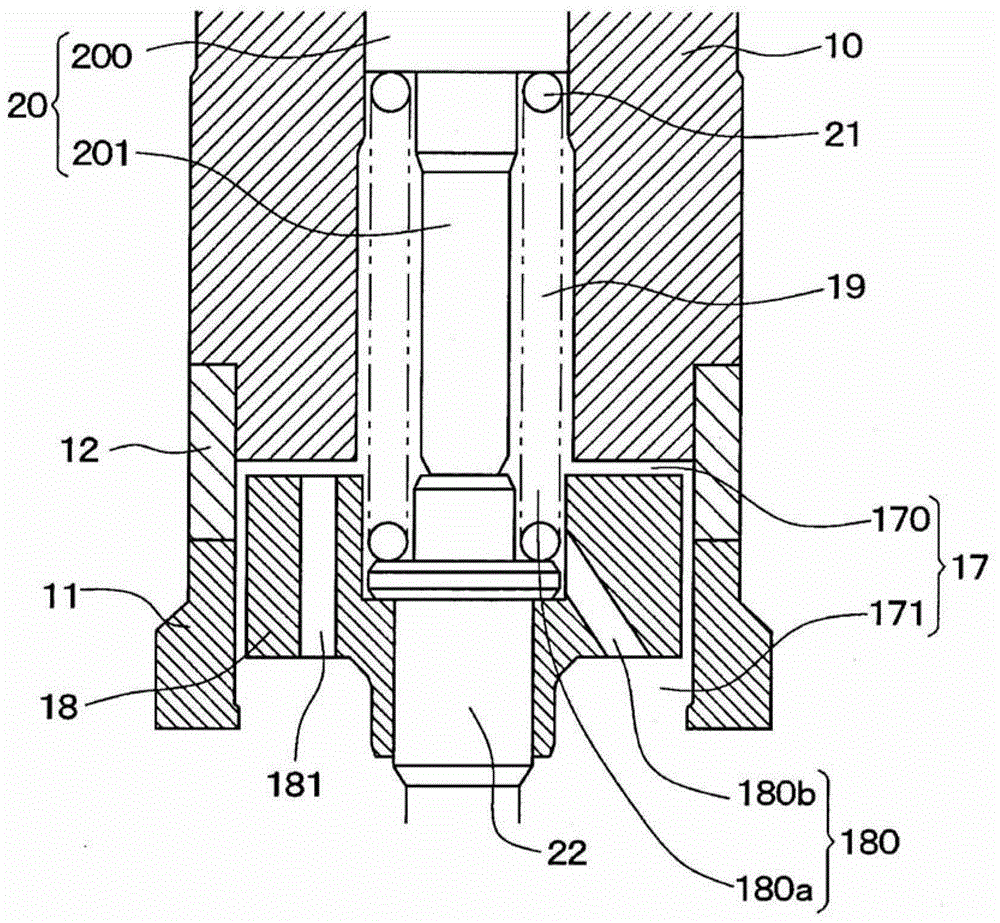
[0022] refer to figure 1 and figure 2 , the stator core 10 is configured as a cup-shaped body and made of a magnetic metal material, and the sleeve 11 is configured as a cylindrical tubular body and made of a magnetic metal material. The stator core 10 and the sleeve 11 are integrated together by a collar 12 configured in a cylindrical tubular form and made of a non-magnetic metal material. Spe...

no. 2 example )

[0052] A second embodiment of the present invention will be described. In the present embodiment, the structure of the armature 18 is changed, and the rest of the solenoid valve is the same as that of the first embodiment. Therefore, in the following discussion, only the different parts of the solenoid valve from the first embodiment will be described.

[0053] like Figure 5 and Image 6 As shown, in the surface area of ​​the armature 18 , the connection groove 28 extends from each second communication channel 181 towards the radial center of the armature 18 opposite the stator core 10 .

[0054] Because each second communication channel 181 is provided with the connection groove 28, the movement of the liquid between the second communication channel 181 and the first spring chamber 19 becomes easy, ie, improved. Therefore, generation of cavitation in the first armature chamber 170 and the first spring chamber 19 when the armature 18 is moved in a direction away from the s...

no. 3 example )

[0056] A third embodiment of the present invention will be described. In the current embodiment, the plate 29 is added, and the rest of the structure of the solenoid valve is basically the same as that of the first embodiment. Therefore, in the following discussion, only the different parts of the solenoid valve from the first embodiment will be described.

[0057] like Figure 7 As shown, a plate 29 configured in a cylindrical tubular form (also referred to as an annular form) is set as an opposing member (also referred to as an armature side opposing member or as an opposing member) in a second armature chamber 171. simply referred to as opposing components). The plate 29 is fixed to the guide 13 by, for example, press fitting.

[0058] Furthermore, one end surface of the plate 29 is axially opposed to a corresponding surface portion of the armature 18 arranged on the axial side where the second armature chamber 171 is located. The size of the gap (ie, the distance) betw...


PUM


Abstract

An armature chamber receives an armature and includes a first armature chamber, which is placed adjacent to one end surface of the armature and is communicated with a spring chamber, and a second armature chamber, which is placed adjacent to the other end surface of the armature, which is opposite from the one end surface of the armature. The armature includes a primary communication passage that communicates between the first armature chamber and the second armature chamber. An opening end of the primary communication passage, which opens on a side where the first armature chamber is located, is placed at a corresponding location of the armature, which is opposed to the spring chamber.

Description

technical field [0001] The invention relates to a solenoid valve. Background technique [0002] In previously proposed solenoid valves, when the coil is energized, the armature is magnetically attracted to the stator core by magnetic attraction. In contrast, when the coil is de-energized, the armature is driven towards the side opposite the stator core by the thrust of the spring. The spring is accommodated in a spring chamber formed in the stator core, and the armature is accommodated in the armature chamber. [0003] The armature chamber is divided into two chambers by the armature. Specifically, the armature chamber is divided into: a first armature chamber arranged adjacent to one end surface of the armature and communicating with the spring chamber; and a second armature chamber arranged adjacent to the other end surface of the armature (see For example JP2007-278365A). [0004] With this previously proposed solenoid valve, the pressure of the first armature chamber...

Claims


Application Information

Patent Timeline
Patent Type & Authority Patents(China)
IPC IPC(8): F02M59/46
CPCF02M59/366F16K31/0658
Inventor 有川文明三俣直树
Owner DENSO CORP
Why Eureka
Eureka Blog
Learn More