Riveting nut

A technology for riveting nuts and nut bodies, applied in the directions of nuts, connecting members, threaded fasteners, etc., can solve problems such as the inability to fix the nut body and the falling off of the card body.

Inactive Publication Date: 2013-12-04
珠海富菱电子科技有限公司
View PDF6 Cites 1 Cited by
  • Summary
  • Abstract
  • Description
  • Claims
  • Application Information

AI Technical Summary

Problems solved by technology

[0009] But, because this rivet nut is connected with the chuck by mutually detachable nut body, and between the nut body and the chuck is only connected with the chuck through the card body of the elastic jaw at the

Method used


Image

  • Riveting nut
  • Riveting nut
  • Riveting nut

Examples


no. 1 example

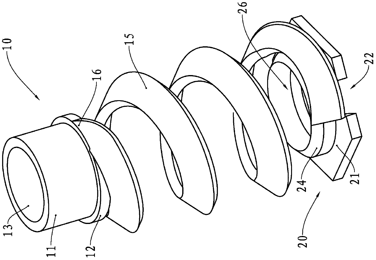
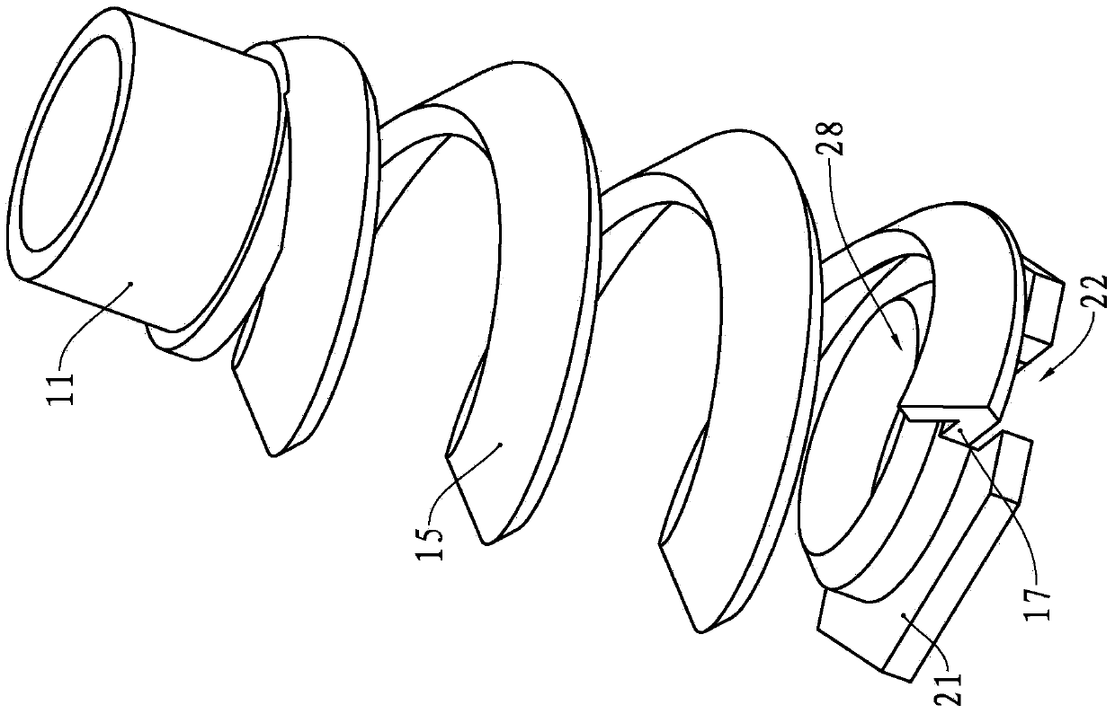
[0032] see figure 1 and figure 2 , The riveting nut 10 of the present embodiment has a circular cylindrical nut body 11, a ring flange 12 is provided at the lower end of the nut body 11, a through hole 13 is formed in the middle part of the nut body 11, and internal threads are provided on the inner wall of the nut body 11 ( figure 1 and figure 2 not shown). When the bolt is screwed into the nut body 11 , the external thread on the bolt cooperates with the internal thread of the nut body 11 , and as the bolt rotates, relative displacement will occur between the bolt and the nut body 11 .

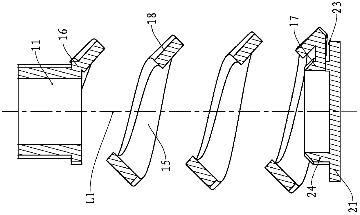
[0033] The lower end of the nut body 11 is provided with a helical connecting portion 15, the first end 16 of the connecting portion 15 is fixedly connected with the flange 12 of the nut body 11, and the connecting portion 15 is formed from the flange 12 of the nut body 11 along the edge of the nut body 11. Axial helical extension.

[0034] The lower end of the connecting portion 15 i...

no. 2 example

[0047] see Figure 8 , The riveting nut 40 of this embodiment has an annular columnar nut body 41 , and a flange 42 is provided at the lower end of the nut body 41 . The middle part of the nut body 41 is provided with a through hole 43, and the inner wall of the nut body 41 is provided with an internal thread ( Figure 8 not shown).

[0048] The connecting portion 45 is located below the nut body 41 , and the first end 46 of the connecting portion 45 is fixed on the outer wall of the flange 42 . Below the connecting portion 45 is a fixing portion 50, which includes a regular hexagonal columnar fixing plate 51 and a positioning ring 55 located on the end surface of the fixing plate 51 close to the nut body 41, the positioning ring 55 is in the shape of a circular column. Moreover, a notch 52 is also provided on the fixing plate 51 . The middle part of the fixing part 50 is provided with a through hole, which passes through the fixing plate 51 and the positioning ring 55 , so...

no. 3 example

[0053] see Figure 9 The riveting nut 60 of this embodiment has a nut body 61 and a fixing portion 70 located below the nut body 61 , and the nut body 61 and the fixing portion 70 are connected by a connecting portion 65 . The nut body 61 is in the shape of a ring column, and a through hole 63 is provided in the middle thereof, and an internal thread ( Figure 9 not shown).

[0054] The connecting portion 65 is helical, and its first end 66 is fixed on the outer wall of the nut body 61 and fixed on an end of the nut body 61 away from the fixing portion 70 . The connecting portion 65 extends from the outer wall of the nut body 61 along the axial direction of the nut body 61 .

[0055] The fixing part 70 has a regular hexagonal columnar fixing plate 71 and a positioning ring 75 located on the end surface of the fixing plate 71 close to the nut body 61 , and a notch 72 is provided on the fixing plate 71 . The positioning ring 75 is circular and cylindrical, and the second end ...


PUM


Abstract

The invention provides a riveting nut which is provided with a nut body. The inner wall of the nut body is provided with an internal screw thread; the riveting nut also comprises a connecting part; a first end of the connecting part is fixed on the nut body; the connecting part is of a spiral shape; the connecting part extends along the axial direction of the nut body; the riveting nut is also provided with a fixing part; the fixing part comprises a fixing plate and a positioning ring positioned on one end face of the fixing plate; a second end of the connecting part is fixed on the positioning ring; and the fixing part is provided with a through hole running through the fixing plate and the positioning ring. The riveting nut provided by the invention can be conveniently arranged on a board which is inconvenient to place a common nut, is firmly connected with a bolt and is difficult to fall off.

Description

technical field [0001] The invention relates to the field of assembly tools, in particular to a riveting nut. Background technique [0002] The equipment used in people's life and production process is usually composed of multiple parts, and the fixed connection between multiple parts is usually realized by using fixed workpieces. In addition, when people realize the connection between two objects, they often need to use fixed workpieces. For example, people need to install locks on the door, usually offer threaded holes on the door, and set the through hole for the bolt to pass on the lock, use the bolt to pass through the through hole and then screw into the threaded hole, so there is a gap between the lock and the door. The fixed connection is realized by bolts. [0003] In addition to using threaded connections, common fixed connection methods include riveting, gluing, welding, etc. People choose the appropriate connection method according to the needs of actual use. ...

Claims


Application Information

Patent Timeline
IPC IPC(8): F16B37/06
Inventor 陈业朋
Owner 珠海富菱电子科技有限公司
Why Eureka
Try Eureka