LED (Light Emitting Diode) ceiling lamp

A technology of LED ceiling lamps and LED lamp panels, applied in lighting and heating equipment, semiconductor devices of light-emitting elements, point light sources, etc.

Inactive Publication Date: 2013-04-03
XIAN XINWEI INFORMATION TECH
View PDF0 Cites 0 Cited by
  • Summary
  • Abstract
  • Description
  • Claims
  • Application Information

AI Technical Summary

Problems solved by technology

When the lamp tube is broken, the above-mentioned installation also requires the above-mentioned process, which brings a lot of inconvenience to ordinary families

Method used


Image

  • LED (Light Emitting Diode) ceiling lamp
  • LED (Light Emitting Diode) ceiling lamp
  • LED (Light Emitting Diode) ceiling lamp

Examples


Embodiment 1

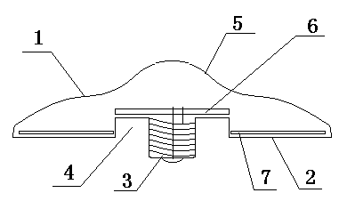
[0019] Such as figure 1 As shown, an LED ceiling lamp, at least the lamp body includes: a light-transmitting shell surface 1, a fixed base surface 2 and a lamp cap 3, the middle surface 5 of the light-transmitting shell surface 1 is high, and the thickness of the middle surface gradually decreases around it, forming a streamlined curved surface . The fixed base surface 2 is an inner concave cavity 4 structure, and the lamp cap 3 protrudes in the inner concave cavity 4, and the cavity mouth of the inner concave cavity 4 is larger than the lamp socket connected to a standard lamp cap, such as E27 or the like. The middle surface 5 and the lamp cap 3 are on the center line of the lamp body. Lamp holder 3 is screw type.

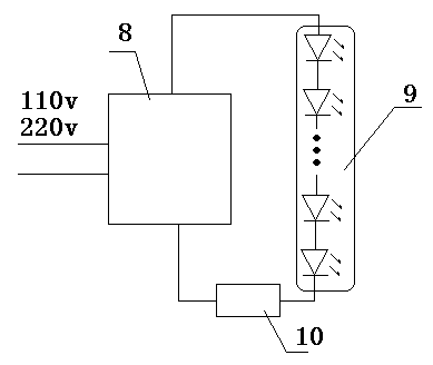
[0020] Such as figure 2 As shown, there are LED driving circuit and LED lamp board in the lamp body, the LED driving circuit is a constant current linear driving circuit 10, and the constant current linear driving circuit 10 and the LED9 connected in series on...

Embodiment 2

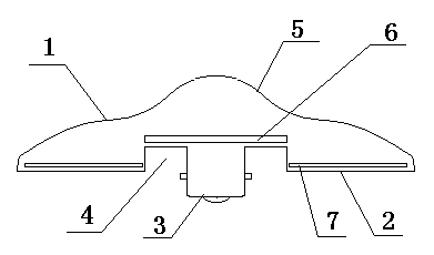
[0023] Such as image 3 As shown, the difference between Embodiment 2 and Embodiment 1 is that the lamp cap 3 is a hook type.


PUM


Abstract

The invention relates to an LED (Light Emitting Diode) ceiling lamp, which is characterized in that a lamp body at least comprises a light-transmitting shell surface (1), a fixed base surface (2) and a lamp cap (3), wherein the fixed base surface is provided with an inner concave cavity (4) which is connected with the lamp cap (3). The LED ceiling lamp has the characteristics of high efficiency, low cost, convenience in installation and the like.

Description

technical field [0001] The invention relates to a ceiling lamp, in particular to an LED ceiling lamp. Background technique [0002] Existing ceiling lamps are mostly fluorescent tube structures, including a base, a lamp tube, and a lampshade. The lampshade needs to absorb part of the light, but it cannot be without it. Without the lampshade, it will affect the appearance. The ceiling lamp formed by the existing LED lamp also adopts the above-mentioned structure, and the same lampshade will absorb part of the light. [0003] In fact, the above-mentioned structure also has the complexity of the installation process and the increase of the cost. For example, in order to install the base, a professional electrician is required, and electrical tools such as an electric drill are used to install the base. After the base is installed, the lamp tube is put in, and the lampshade is fixed. When the lamp tube is broken, the above-mentioned installation also requires the above-mention...

Claims


Application Information

Patent Timeline
Patent Type & Authority Applications(China)
IPC IPC(8): F21S8/04F21V17/00F21V23/00F21Y101/02F21Y115/10
Inventor 刘珉恺
Owner XIAN XINWEI INFORMATION TECH
Why Eureka
Try Eureka