A chip motherboard processing system

A processing system and motherboard technology, which is applied in the direction of assembling printed circuits with electrical components, can solve the problems of reducing welding efficiency, reducing comfort, and unable to adjust the position of the motherboard, so as to achieve the effect of improving comfort and work efficiency

Inactive Publication Date: 2020-09-22
HARBIN UNIV OF COMMERCE
View PDF1 Cites 0 Cited by
  • Summary
  • Abstract
  • Description
  • Claims
  • Application Information

AI Technical Summary

Problems solved by technology

There are usually multiple welding places on the main board, so when the staff needs to weld different welding places, it is generally necessary to change the position to achieve the best welding state, and the position of the main board is relatively fixed after the device is fixed. Adjust the position of the motherboard according to the welding habits of the staff, thereby reducing the comfort of the staff when welding, and also reducing the welding efficiency.

Method used


Image

  • A chip motherboard processing system
  • A chip motherboard processing system
  • A chip motherboard processing system

Examples


specific Embodiment approach 1

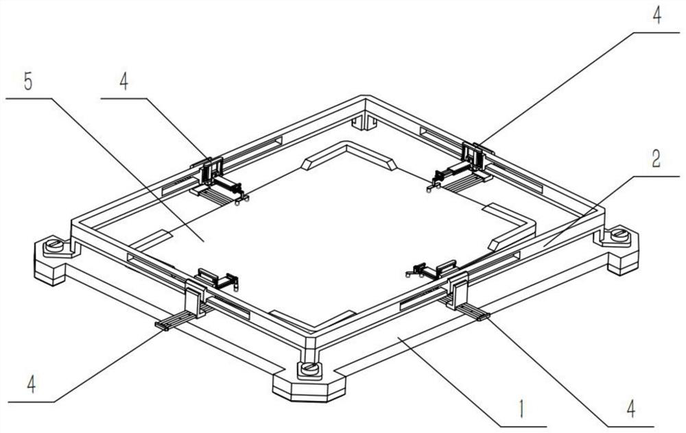
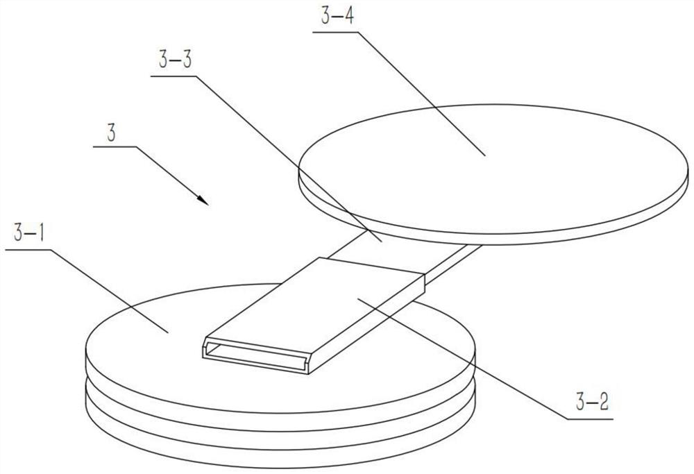
[0035] Combine below Figure 1-11Describe this embodiment, a chip motherboard processing system, including a base 1, an installation frame 2 and a clamping mechanism 4, the installation frame 2 is fixedly connected to the base 1, the chip motherboard processing system also includes a rotating shaft structure 3 and Workbench 5, the rotating shaft structure 3 is rotatably connected to the middle part of the base 1, the workbench 5 is fixedly connected to the upper end of the rotating shaft structure 3, the clamping mechanism 4 is composed of a connecting part 6, an elastic mechanism I7, The sliding part 8, the elastic mechanism II9 and the pressing part 10, the elastic mechanism I7 is fixedly connected to the upper end of the connecting part 6, the sliding part 8 is slidably connected to the elastic mechanism I7, and the elastic mechanism II9 slides Connected in the sliding part 8, the pressing part 10 is slidably connected to the elastic mechanism II9, the clamping mechanism 4 ...

specific Embodiment approach 2

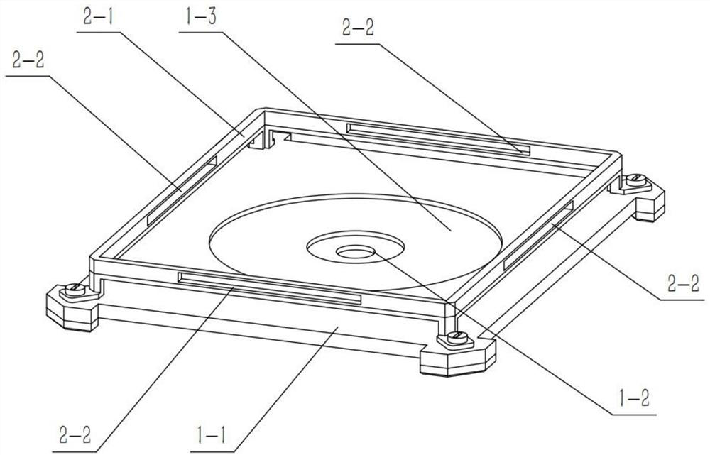
[0038] Combine below Figure 1-11 Describe this embodiment, this embodiment will further explain Embodiment 1, the base 1 includes a bottom plate 1-1, a rotating hole 1-2 and a circular groove 1-3, and the circular groove 1-3 is arranged on the bottom plate 1 -1, the rotating hole 1-2 is set in the middle of the circular groove 1-3, the mounting frame 2 is fixedly connected to the bottom plate 1-1, and the rotating shaft structure 3 is rotatably connected to the In the transfer hole 1-2.

specific Embodiment approach 3

[0040] Combine below Figure 1-11 Describe this embodiment, this embodiment will further explain the second embodiment, the installation frame 2 includes a frame 2-1 and a slideway 2-2, the frame 2-1 is fixedly connected to the bottom plate 1-1, There are four slideways 2-2, and the four slideways 2-2 are respectively arranged on the four sides of the frame 2-1, and the four elastic mechanisms I7 are slidably connected to the four slideways 2-2 respectively. Inside.


PUM


Abstract

The invention relates to a fixing device for circuit board welding, more specifically a chip main board processing system, the device can be placed on the corresponding position of the workbench according to the position of the main board to be welded, when the position of the main board needs to be adjusted, directly Just adjust the position of the workbench. The lower end of the workbench is connected with a rotating shaft structure. The relative position of the workbench can be flexibly adjusted by using the rotating shaft structure. Each clamping mechanism is connected with the workbench. The position adjustment of the workbench will not affect each clamp The fixing effect of the holding mechanism on the main board, and then achieve the purpose of flexibly adjusting the position of the main board according to the welding habits and welding needs of the staff, and then improve the comfort and work efficiency of the staff when welding.

Description

technical field [0001] The invention relates to a fixing device for convenient circuit board welding, in particular to a chip main board processing system. Background technique [0002] For example, the publication number is CN104093281B, which is a fixing device convenient for circuit board welding, including a base plate, a front baffle, a right baffle, a rear baffle, a left baffle, and a sealing plate. The top of the base plate is provided with a positioning cavity, and the The bottom end of the base plate is provided with strip grooves and welding holes, and at least two locking devices are provided in the cavity; the advantage of the present invention is that the circuit board is fixedly connected to the positioning cavity provided on the base plate through the locking devices The required components of the circuit board are welded through the strip grooves and welding holes provided at the rear end of the base plate. During welding, because the circuit board is locked ...

Claims


Application Information

Patent Timeline
Patent Type & Authority Patents(China)
IPC IPC(8): H05K3/34
CPCH05K3/34
Inventor 韩雪娜
Owner HARBIN UNIV OF COMMERCE
Why Eureka
Try Eureka