

Run-on plate
A technology of arc striker and arc striker, which is applied in the direction of electrical components, electric switches, circuits, etc., can solve the problems of hindering arc movement, poor switch disconnection performance, and low production efficiency, so as to simplify the combination of parts and increase The effect of arc striking magnetic field strength and improving assembly efficiency
- Summary
- Abstract
- Description
- Claims
- Application Information
AI Technical Summary
Problems solved by technology
Method used
Image

Examples
Embodiment 1
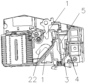
[0028] see figure 1 The arc-starting plate disclosed in the present invention includes an arc-starting piece 2, which is obliquely arranged below the moving contact 1, and the lower end of the arc-starting piece 2 is connected to the lower end of the arc extinguishing chamber. The upper end of the arc piece 2 is arranged close to the moving contact 1; and the arc starting support plate 3, the upper end of the arc starting support plate 3 is connected to the upper end of the arc starting piece 2, and the lower end of the arc starting support plate 3 It is in contact with the lower end of the bimetal sheet 5; the contact connection between the arc striker 2 and the arc strike support plate 3 has a substantially horizontal transition section. The horizontal direction mentioned here is not absolutely horizontal, the transition section here only plays the role of connecting the arc striker 2 and the arc strike support plate 3, and keeps them separated by a certain distance, so the ...
Embodiment 2
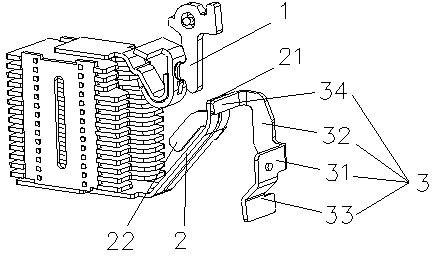
[0036] see figure 2 , on the basis of the first embodiment above, the arc starting plate 2 is provided with a bending portion 22 pointing to the arc extinguishing chamber on the side close to the arc extinguishing chamber, and the bending portion 22 is connected with the arc starting plate A "U"-shaped opening is formed between the upper surfaces of 2, and the direction of the opening points to the arc extinguishing chamber. In order to further strengthen the strength of the arc striking magnetic field, two or more of the bending parts 22 may also be provided on both sides of the upper surface of the arc starting piece 2, of course, when setting the bending parts 22, they must be combined The specific size of the internal space of the circuit breaker and the installation process depend on it. Experiments have proved that the provision of one bent portion 22 can meet the requirements of rapid arc ignition.
[0037] The bending part 22 in this embodiment is a sheet structure, ...
PUM
 Abstract
Description
Claims
Application Information