Eddy speed changer

A transmission and eddy current technology, applied in the field of eddy current transmission, can solve the problems of inconvenience, conductive ring and magnetic rotor arrangement can not be changed, so as to achieve the effect of reducing load, rationalizing energy and solving waste of energy consumption

Inactive Publication Date: 2013-12-04
SHANGHAI POTEVIO
View PDF4 Cites 3 Cited by
  • Summary
  • Abstract
  • Description
  • Claims
  • Application Information

AI Technical Summary

Problems solved by technology

[0003] Aiming at the problems in the prior art that the arrangement of the conductive ring and the magnetic rotor cannot be changed and that the gap between the conductive ring an

Method used


Image

  • Eddy speed changer
  • Eddy speed changer
  • Eddy speed changer

Examples


Embodiment Construction

[0018] The technical solutions of the present invention will be further described below in conjunction with the accompanying drawings and embodiments.

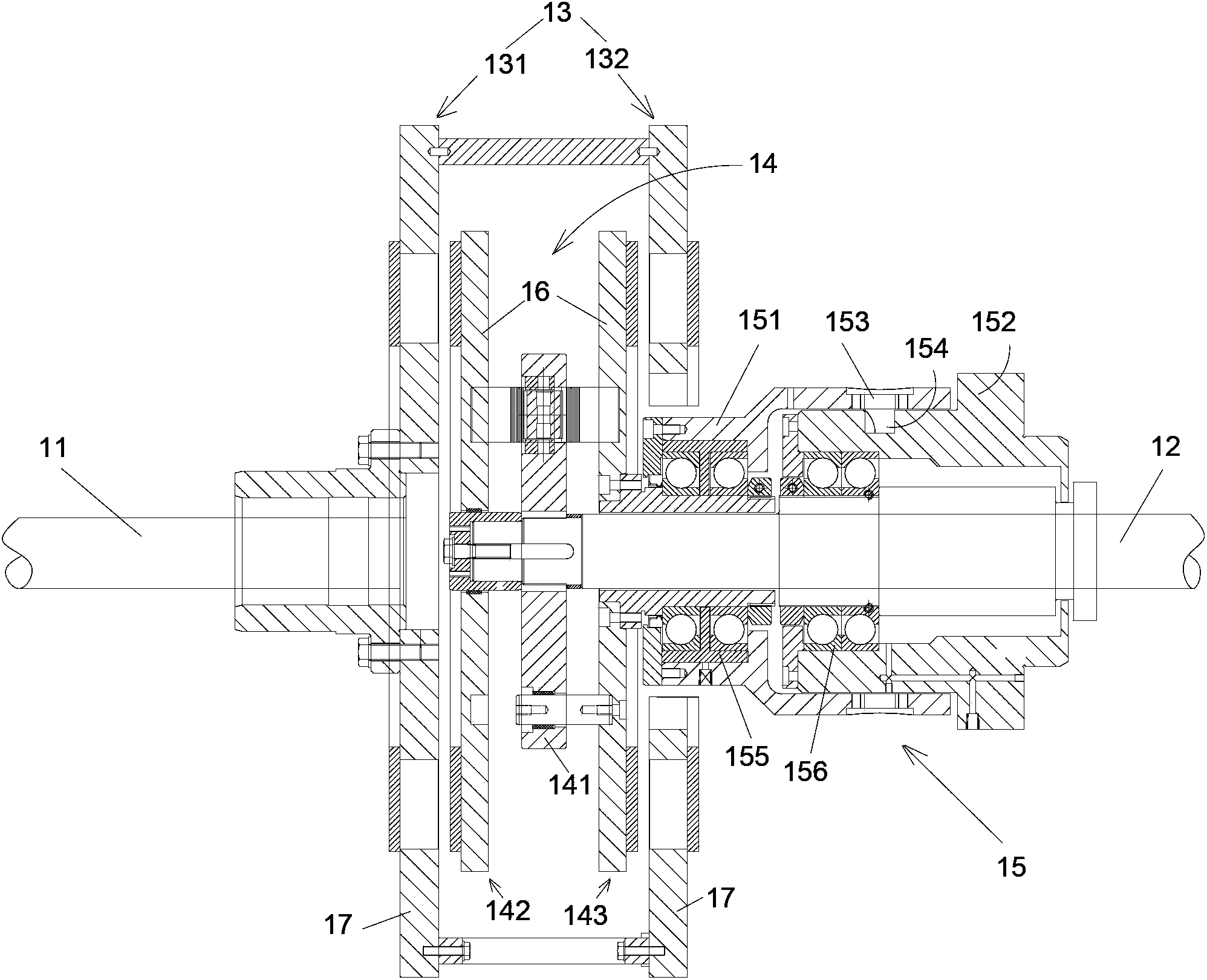
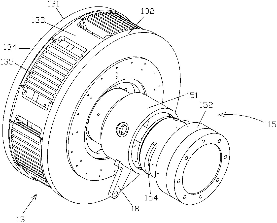
[0019] see figure 1 , figure 2 , image 3 , Figure 4 The vortex transmission shown includes a first rotating shaft 11 and a second rotating shaft 12 arranged horizontally, a rotating outer frame 13, an inner rotor assembly 14 with a central pivot disc 141, a driving mechanism 15 for adjusting the gap, two Conductive ring 16 and two magnetic rotors 17, the first rotating shaft 11 is fixedly connected with the rotating outer frame 13, the second rotating shaft 12 is fixedly connected with the central pivoting disc 141, the inner rotor assembly 14 is arranged in the rotating outer frame 13, and the rotating outer frame The two ends of 13 are provided with a first tray 131 and a second tray 132, and the outer side of the inner rotor assembly 14 is provided with a third tray 142 and a fourth tray 143, between the first tray 13...


PUM


Abstract

The invention discloses an eddy speed changer which comprises a first rotating shaft, a second rotating shaft, a rotating outer frame, an inner rotor assembly with a central pivot turntable, a driving mechanism, two conducting rings and two magnetic rotors. The driving mechanism comprises an outer sleeve and an inner sleeve which are arranged on the second rotating shaft in a sleeved mode, a cam is arranged on the inner side of the outer sleeve, a groove is formed in the peripheral face of the inner sleeve, the inner sleeve is sleeved with the outer sleeve, the cam extends into the groove, the cam slides in the groove to drive the outer sleeve to move in the axial direction of the second rotating shaft, therefore, a fourth disk position is driven to make axial movement, finally, a third disk position and the fourth disk position on the outer side of the inner rotor assembly are made to move relative to a first disk position and the third disk position to change the size of a gap, and the output rotating speed is controlled. The conducting rings and the magnetic rotors are arrayed in different disk positions, so that the eddy speed changer can further meet different filed installation requirements.

Description

technical field [0001] The present invention relates to the eddy current speed change technology, more specifically, relates to a kind of eddy current speed changer. Background technique [0002] The connection device between the existing drive shaft and the load shaft is generally a mechanical part such as a coupling or a reduction box, that is, a hard connection between the two shafts. When the drive shaft rotates, the load shaft is driven by the hard connection device. turn. However, due to the hard connection between the drive shaft and the load shaft, precise alignment is required, which requires increased manufacturing precision and high vibration. The eddy current transmission technology, referred to as ECT, is the latest revolutionary transmission technology in recent years. This technology has the advantages of high efficiency, energy saving, environmental protection, and high reliability. It can meet the requirements of safe, reliable, and low failure rates for pr...

Claims


Application Information

Patent Timeline
IPC IPC(8): H02K49/04
Inventor 王允强袁吾均郑迪陈建平华敏张文奇杨奕
Owner SHANGHAI POTEVIO
Why Eureka
Try Eureka