Corn picking composite roller

A compound roller and corn technology, applied in the direction of cutters, agricultural machinery and implements, applications, etc., can solve the problems of low operating efficiency of the whole machine and low efficiency of pulling stems, and achieve the effect of reducing effective blows and reducing grain damage

Active Publication Date: 2013-12-11
HEBEI ZHONGNONGBOYUAN AGRI EQUIP CO LTD
View PDF6 Cites 10 Cited by
  • Summary
  • Abstract
  • Description
  • Claims
  • Application Information

AI Technical Summary

Problems solved by technology

The disadvantage is that the efficiency of pulling the stem is

Method used


Image

  • Corn picking composite roller
  • Corn picking composite roller
  • Corn picking composite roller

Examples


Embodiment 1

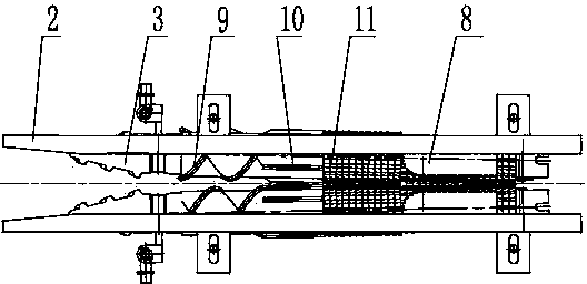
[0029] Attached figure 2 It can be seen that the structure of the present invention specifically includes two symmetrically arranged counter-rotating rollers with a gap between the two counter-rotating rollers. The left end of the counter-rotating roller is a guide cone, and the right side of the guide cone is a stem section 10, which The counter-rotating rollers at section 10 are evenly distributed in the circumferential direction with shifting teeth, which extend along the radial direction of the counter-rotating roller, and the structure of the shifting teeth is a long steel sheet. An introduction section 9 is provided between the stem pulling roller 10 and the guide cone, and a guide spiral is arranged on the outer wall of the rotating roller at the introduction section 9. A stripping section 11 is provided on the right side of the pulling stem section 10, the surface of the counter-rotating roller at the stripping section 11 is a toothed structure made of rubber material, ...

Embodiment 2

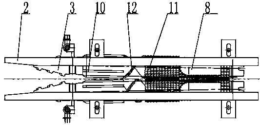
[0033] As attached image 3 As shown, on the basis of the first embodiment, a feeding section 12 is added between the pulling stem section 10 and the peeling section 11, and the feeding section 12 is provided with guiding spiral edges on the outer wall of the roller.

Embodiment 3

[0035] As attached Figure 4 As shown, this structure is based on the second embodiment, the introduction section 9 is eliminated, and the introduction section 9 is replaced by the spiral edge of the guide cone to realize the feeding of straw.

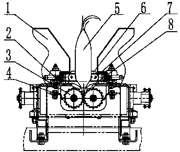
[0036] For the composite roller of the present invention, it is necessary to add two reel chains 7 during use. The two reel chains 7 are symmetrically arranged above the counter-rotating roller. The reel chain 7 is a closed chain, and the outer sides of the chains are respectively The reel is composed of the auxiliary plate 13 and the scraper 6. The chain is driven by three sprockets, so that the front end of the chain forms a horn-shaped entrance, and the middle and rear parts are parallel sections.

[0037] In order to ensure that the straw on the counter-rotating roller sticks to the surface of the roller, a grass cleaning knife 4 is added. The grass cleaning knife 4 is arranged on the outside of the counter-rotating roller and fixed on t...


PUM


Abstract

The invention discloses a corn picking composite roller, and belongs to the field of corn harvest machines. The corn picking composite roller comprises two oppositely-rotating roller bodies, the two oppositely-rotating roller bodies are arranged in parallel, a gap is reserved between the two oppositely-rotating roller bodies, a guiding cone is arranged on the front end portion of each oppositely-rotating roller body, the spiral directions of the two guiding cones are opposite, the right sides of the guiding cones are stem pulling sections, and pulling teeth are arranged at the positions of the stem pulling sections in the peripheral direction. According to the corn picking composite roller, a traditional stem pulling roller and a traditional ear picking roller body are improved, the functions of stem pulling, ear picking, skin peeling and sundry removing are integrated, the advantages of the traditional stem pulling roller body and the traditional ear picking roller body are integrated in the corn picking composite roller, therefore, effective impact of the stem pulling roller on corn ears can be reduced, and the strong capture capacity to broken stems is achieved.

Description

Technical field [0001] The invention belongs to the field of corn harvesting machinery, in particular to a composite roller used for corn picking, which integrates the functions of stem pulling, ear picking, peeling and cleaning. Background technique [0002] In the current corn harvesting machinery, the harvesting methods used by the harvesting header mainly include the following three methods: [0003] 1) Hexagonal squeeze and pull the stem and the chain is forced to feed the stem roller. (Application No. / Patent No.: 201220029821) Its advantages are high stem pulling rate and strong adaptability to harvest time, so the whole machine has high operating efficiency. The disadvantages are the grain damage caused by the mechanical impact on the corn at the moment of picking ears, and the reduction of the ability to clean broken stalks caused by the large-scale sealing of the guide plate on the stalk roll. [0004] 2) The four-sided tooth pierces the stem and the chain is forced to fee...

Claims


Application Information

Patent Timeline
IPC IPC(8): A01D45/02A01D43/00
Inventor 雍凤文张国彬周浩马洪宗
Owner HEBEI ZHONGNONGBOYUAN AGRI EQUIP CO LTD
Why Eureka
Try Eureka