
In-pipe downhole variable-diameter limiter blocking and isolating device

A technology of isolation device and limiter, which is applied in sealing/isolation, wellbore/well components, earthwork drilling and production, etc. It can solve the problems of delayed sound measurement and resistance, and achieves accurate and controllable expansion and contraction, Avoid the effect of delayed sound change

Active Publication Date: 2016-02-10
BC P INC CHINA NAT PETROLEUM CORP +1
View PDF6 Cites 0 Cited by
  • Summary
  • Abstract
  • Description
  • Claims
  • Application Information

AI Technical Summary

Problems solved by technology

[0003] The technical problem to be solved by the present invention is to overcome the problems in the background technology that the drilling fluid will be retained in the casing of the clear water displacement technology and the phenomenon of delayed sound measurement and variable resistance is easy to occur, and to provide a downhole variable diameter limit body resistance in the pipe. Cut-off isolation device, the downhole variable-diameter limiter blocking isolation device in the pipe, after the cementing operation is completed, ensure that the pipe is filled with clean water to avoid the occurrence of delayed sound change resistance

Method used


Image

  • In-pipe downhole variable-diameter limiter blocking and isolating device
  • In-pipe downhole variable-diameter limiter blocking and isolating device

Examples


Embodiment 1

[0017] Example 1: Apricot 3-But 4-E68 well

[0018] The design depth of the well: 1239 meters, the position of the cement surface control tool: 894 meters. On September 16, 2012, variable diameter cementing rubber plugs were used for cementing construction. The designed replacement volume of the second replacement: 11.4 cubic meters, and the actual replacement volume of the second replacement: 11.4 cubic meters. Acoustic change detection was carried out after 20 days, and logging was successful once.

[0019] The designed replacement volume of the second replacement in this well is consistent with the actual replacement volume, indicating that the variable diameter cementing rubber plug rubber body has a high degree of contact with the casing wall, which effectively separates and seals the drilling fluid in the casing from the clear water and ensures that the ball is closed The secondary displacement fluid runs synchronously to avoid the retention of drilling fluid in the casing....

Embodiment 2

[0020] Example 2: Apricot 3-40-E66 well

[0021] The design depth of the well: 1241 meters, the position of the cement surface control tool: 894 meters. Using variable diameter cementing rubber plugs for cementing construction, the designed replacement volume of the second replacement: 11.4 cubic meters, and the actual replacement volume of the second replacement: 11.4 cubic meters. Acoustic change detection was carried out after 20 days, and logging was successful once.

[0022] The designed replacement volume of the second replacement in this well is consistent with the actual replacement volume, indicating that the variable diameter cementing rubber plug rubber body has a high degree of contact with the casing wall, which effectively separates and seals the drilling fluid in the casing from the clear water and ensures that the ball is closed The secondary displacement fluid runs synchronously to avoid the retention of drilling fluid in the casing. A successful acoustic varia...


PUM


Abstract

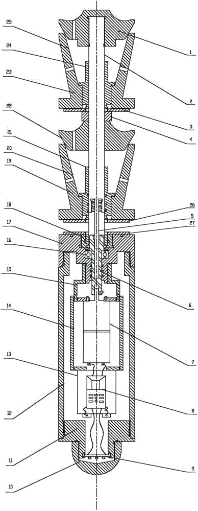
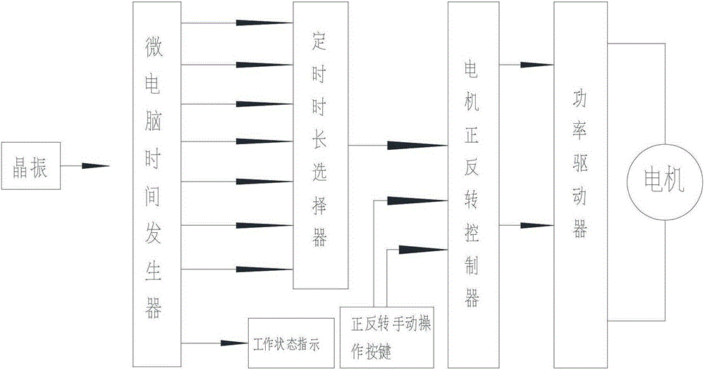
The invention relates to an in-pipe downhole variable-diameter limiter blocking and isolating device. It mainly solves the problems in the prior art that the drilling fluid will remain in the casing of the clear water displacement technology and the phenomenon of delayed sound measurement and resistance phenomenon is easy to occur. It is characterized in that: the front end of the central shaft is threadedly connected to the primary gland, the central axis at the rear of the primary gland is fixedly connected with the primary limiting body, the primary positioning ring, and the height adjustment ring in sequence, and the outside of the primary limiting body There is a first-level rubber body; the central axis of the lower part of the height adjustment ring is connected with the second-level gland, and the central axis of the lower part of the second-level gland is fixedly connected with the second-level limit body, the second-level positioning ring, and the third-level positioning ring; the second-level limit The body is covered with a secondary rubber body; the inner cavity at the rear of the central shaft is connected with a four-head trapezoidal buckle screw and a reduction motor; the motor is connected with a controller. The downhole variable-diameter limiter in the pipe is a blocking and isolating device. After the cementing operation is completed, the pipe is filled with clean water to avoid the occurrence of delayed sound change and resistance.

Description

technical field [0001] The invention relates to an isolating device in the field of petroleum engineering well cementing, in particular to a blocking and isolating device of an in-pipe downhole variable-diameter limiting body. Background technique [0002] At present, in the cementing operation of petroleum engineering, the cementing displacement process adopts the clean water displacement technology. The technical scheme of cementing displacement fluid is as follows: clean water + drilling fluid is used for the first displacement, and clean water is used for the second displacement. During a displacement process, a section of clean water is first replaced (the design volume of clean water is from 80 meters above the tool to the inner volume of the casing of the floating hoop), and then the drilling fluid is replaced until it hits pressure. After the completion of a displacement operation, the liquid in the pipe is clean water and drilling fluid . The second displacement u...

Claims


Application Information

Patent Timeline
Patent Type & Authority Patents(China)
IPC IPC(8): E21B33/13
Inventor 李国庆韩昌郭金平齐玉龙周彬
Owner BC P INC CHINA NAT PETROLEUM CORP
Learn More