High temperature heat storage system

A heat storage system and high temperature technology, applied in the field of energy storage, can solve the problems of low heat storage efficiency, achieve the effects of improving heat storage efficiency, avoiding mixing, and convenient operation

Active Publication Date: 2019-09-20
中盐华能储能科技有限公司
View PDF5 Cites 3 Cited by
  • Summary
  • Abstract
  • Description
  • Claims
  • Application Information

AI Technical Summary

Problems solved by technology

[0005] The present invention aims to solve the problem of low heat storage efficiency in the prior art due to the mixing of liquid media of different temperature levels in the high temperature heat storage system during the heat storage process

Method used


Image

  • High temperature heat storage system
  • High temperature heat storage system

Examples


Embodiment 1

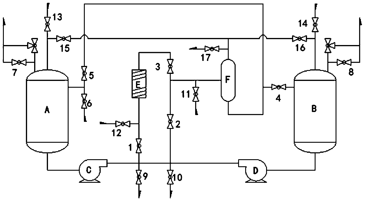
[0031] Such as figure 1 As shown, the present invention provides a high-temperature heat storage system, which includes a low-temperature tank A, a high-temperature tank B, a heat tracer E and a gas-liquid separator F, wherein the exhaust port and the inlet of the low-temperature tank A and the high-temperature tank B The liquid ports are preferably arranged at the tops respectively, and the liquid outlets of the low-temperature tank A and the high-temperature tank B are preferably arranged at the respective bottoms; the exhaust ports of the low-temperature tank A, the high-temperature tank B and the gas-liquid separator F are all provided with exhaust valves , that is to say, the outlet of the low-temperature tank A is provided with a low-temperature exhaust valve 7, the outlet of the high-temperature tank B is provided with a high-temperature exhaust valve 8, and the outlet of the gas-liquid separator F is provided with a gas Liquid exhaust valve 17; the first liquid inlet v...

Embodiment 2

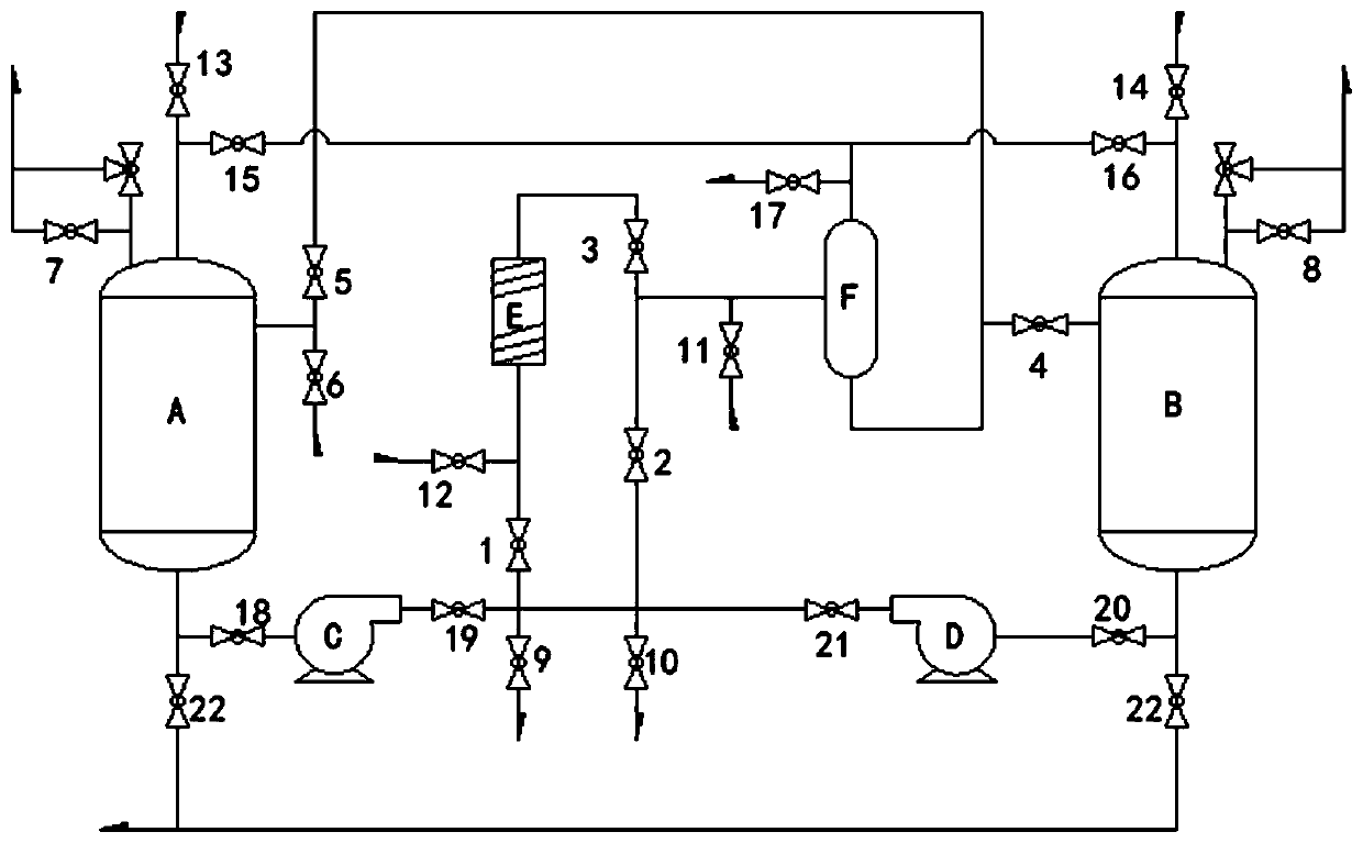
[0063] Such as figure 2 As shown, the structure and principle of the high-temperature heat storage system described in this embodiment are the same as those in Embodiment 1, and will not be repeated in this embodiment. The difference is that, in order to avoid the impact of the heat storage fluid on the cryopump C and the high temperature pump D during shutdown, the inlet and outlet of the cryopump C are provided with a sixth valve 18 and a seventh valve 19 respectively, and the outlet of the cryopump C The seventh valve 19 communicates with the inlet of the first valve 1, the second valve 2 and the first heat exchange valve 9 respectively; the inlet and outlet of the high temperature pump D are respectively provided with an eighth valve 21 and a ninth valve 20, and the high temperature pump D The outlet of D communicates with the inlets of the first valve 1 , the second valve 2 and the second heat exchange valve 10 respectively through the ninth valve 20 .

[0064] Preferab...


PUM


Abstract

The invention relates to the field of energy storage, and provides a high-temperature heat accumulation system. The system comprises a low-temperature tank, a high-temperature tank, a heat tracing device and a gas-liquid separator, wherein a first liquid inlet valve of the low-temperature tank selectively communicates with outlets of an external heat source, a cold source and a heat accumulation liquid source, and a second liquid inlet valve of the gas-liquid separator and a third liquid inlet valve of the heat tracing device selectively communicate with the outlets of the external heat sourceand the cold source separately; a liquid drainage port of the low-temperature tank communicates with a first valve, a second valve and a first heat exchange valve through a low-temperature pump separately; the first valve and the third liquid inlet valve communicate with a third valve through the heat tracing device, and the second valve, the third valve and a second liquid inlet valve communicate with liquid inlet ports of the high-temperature tank and the low-temperature tank through the gas-liquid separator separately; a liquid outlet port of the high-temperature tank communicates with thefirst valve, the second valve and a second heat exchange valve through a high-temperature pump separately; and the first heat exchange valve and the second heat exchange valve communicate with inletsof the external heat source and the cold source separately. The high-temperature heat accumulation system is capable of avoiding mixing in heat accumulation liquids with different temperature grades,so that the heat accumulation efficiency is increased.

Description

technical field [0001] The invention relates to the technical field of energy storage, in particular to a high-temperature heat storage system. Background technique [0002] The world is facing dual pressures from energy and the environment. In order to coordinate the relationship between social development and natural environment protection, it has become the consensus of people from all walks of life to vigorously develop renewable energy and increase the proportion of renewable energy in the energy structure. At present, energy storage technology is the main way to promote the development of renewable energy and solve energy supply problems. One of the most widely used and mature technologies in energy storage technology is high temperature heat storage technology. [0003] High-temperature heat storage technology has the potential for large-scale energy storage, and the heat it stores has a high grade. This heat can not only be used for energy storage alone, but also ca...

Claims


Application Information

Patent Timeline
Patent Type & Authority Patents(China)
IPC IPC(8): F28D20/00
CPCF28D20/0034F28D2020/0069F28D2020/0082Y02E60/14
Inventor 梅生伟薛小代张学林张通陈来军
Owner 中盐华能储能科技有限公司
Why Eureka
Try Eureka