High-heat release gas compressor

A compressor and gas outlet technology, applied in pressure pumps, mechanical equipment, machines/engines, etc., can solve the problems of rising gas temperature and affecting the degree of gas compression, and achieve the effect of low shape requirements and simple structure

Inactive Publication Date: 2013-12-11
ZEROQ SCI & TECH
View PDF5 Cites 0 Cited by
  • Summary
  • Abstract
  • Description
  • Claims
  • Application Information

AI Technical Summary

Problems solved by technology

[0002] Existing gas compressors, whether it is a volumetric gas compressor or a speed gas compressor, will generate a lot of heat during the process of compressing gas, which will cause the temperature of the gas to rise, thereby affecting the degree of gas compression

Method used


Image

  • High-heat release gas compressor
  • High-heat release gas compressor
  • High-heat release gas compressor

Examples


Embodiment 1

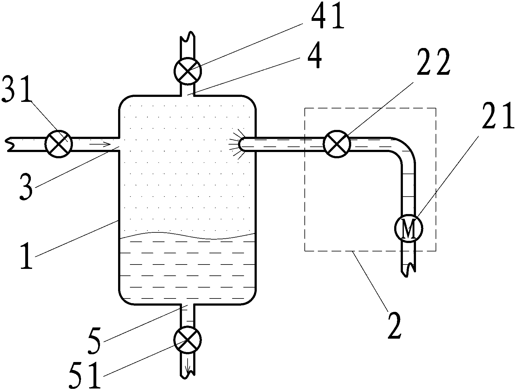
[0028] Such as figure 1 The large exothermic compressor shown includes a container 1 and a timing liquid supply unit 2. The container 1 is provided with a gas inlet 3, a gas outlet 4, a liquid outlet 5 and a liquid inlet, and a control is provided at the gas inlet 3. Valve 31. A control valve 41 is provided at the gas outlet 4, a control valve 51 is provided at the liquid outlet 5, and the liquid outlet of the timing liquid supply unit 2 is in communication with the liquid inlet.

[0029] The working engineering of this embodiment is:

[0030] 1) Air intake process: close the control valve 41, open the control valve 31 and the control valve 51, the gas enters the container 1 through the gas inlet 3 until the liquid in the container 1 is completely Discharge, the control valve 51 is closed, and the gas continues to be filled into the container 1 to reach the set pressure state;

[0031] 2) Compression process: the control valves 31, 41, 51 are closed, the timing liquid supply unit 2 ...

Embodiment 2

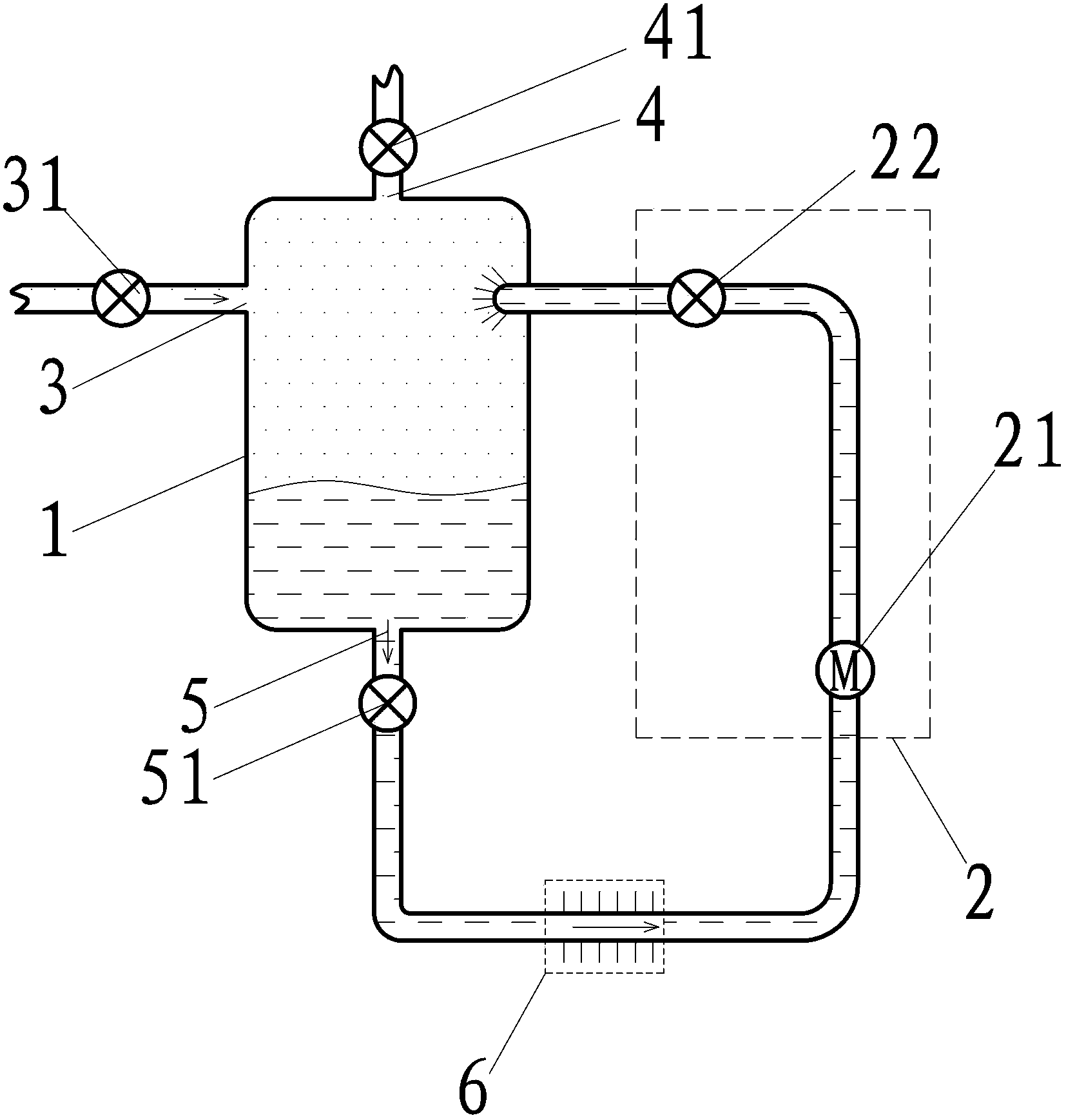
[0034] Such as figure 2 The large exothermic compressor shown, on the basis of Embodiment 1, makes the timing liquid supply unit 2 include a liquid pump 21 and a timing control valve 22, and the liquid pump 21 is controlled by the timing The valve 22 communicates with the liquid inlet, the liquid outlet 5 communicates with the liquid inlet of the timing liquid supply unit 2, and a cooler is provided on the communication channel between the liquid outlet 5 and the liquid pump 21 6.

[0035] Alternatively, the cooler 6 may be arranged on the communication passage between the liquid pump 21 and the timing control valve 22; or may be arranged on the timing control valve 22 and the container instead. 1 on the communication channel between the liquid inlets, or the cooler 6 may not be provided.

[0036] As an alternative embodiment, the liquid outlet 5 of the container 1 may not communicate with the liquid inlet of the timing liquid supply unit 2, and the cooler 6 may not be provided a...

Embodiment 3

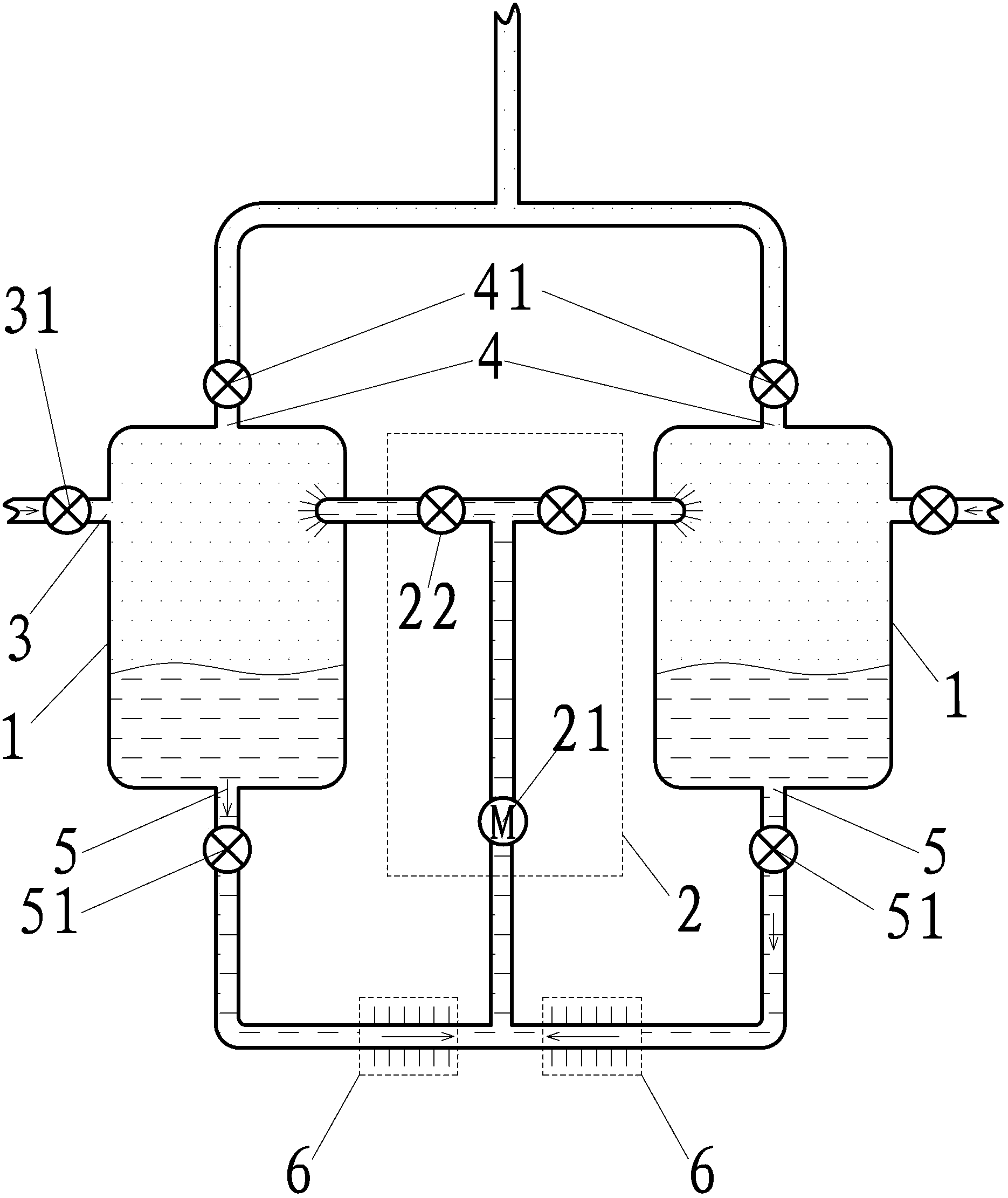
[0039] Such as image 3 In the large exothermic compressor shown, on the basis of the second embodiment, one of the containers 1 is added, two of the containers 1 are arranged in parallel, and the two containers 1 are supplied by one of the timing liquids Unit 2 is connected.

[0040] As a transformable embodiment, the number of containers 1 can be changed to three or more in parallel;

[0041] In all embodiments of the present invention, two or more containers 1 can be provided with reference to this embodiment, so that the two or more containers 1 share the same timing liquid supply unit 2.


PUM


Abstract

The invention discloses a high-heat release gas compressor, which comprises a container and a timing liquid supply and delivery unit, wherein a gas inlet, a gas outlet, a liquid outlet and a liquid inlet are formed in the container; a control valve is arranged at each of the gas inlet, the gas outlet and the liquid outlet; a liquid outlet of the timing liquid supply and delivery unit is communicated with the liquid inlet. According to the high-heat release gas compressor, liquid is used for simultaneously compressing and cooling compressed gas, so that the compression degree of the gas can is higher, and the temperature of the compressed gas is lower.

Description

Technical field [0001] The invention relates to the field of thermal energy and power, in particular to a gas compressor. Background technique [0002] Existing gas compressors, whether they are positive displacement gas compressors or velocity gas compressors, will generate a large amount of heat in the process of compressing the gas, causing the temperature of the gas to rise, thereby affecting the degree of gas compression. Therefore, it is necessary to invent a compressor that can compress low-temperature gas. Summary of the invention [0003] In order to solve the above problems, the technical solution proposed by the present invention is as follows: [0004] A large exothermic compressor, including a container and a timing liquid supply unit. The container is provided with a gas inlet, a gas outlet, a liquid outlet, and a liquid inlet, and the gas inlet, the gas outlet, and the liquid outlet are provided on the container. A control valve is provided at each location, and the...

Claims


Application Information

Patent Timeline
Patent Type & Authority Applications(China)
IPC IPC(8): F04F1/06
Inventor 靳北彪
Owner ZEROQ SCI & TECH
Why Eureka
Try Eureka