Bypass valve having EGR valve

An exhaust gas recirculation valve and exhaust gas recirculation technology, which is applied in the direction of exhaust gas recirculation, valve lift, valve device, etc., can solve the problems of decreased durability of bypass valve related components, reduced nitrogen oxide reduction efficiency, poor exhaust gas cooling efficiency, etc. problems, to achieve the effect of no running error or deformation, improved cooling efficiency, and low running resistance

Active Publication Date: 2013-07-24
UNICK
View PDF3 Cites 0 Cited by
  • Summary
  • Abstract
  • Description
  • Claims
  • Application Information

AI Technical Summary

Problems solved by technology

[0011] However, in the conventional exhaust gas recirculation system 10, since the above-mentioned exhaust gas recirculation valve (not shown) and the bypass valve (not shown) are dispersed and installed, the number of parts used to connect them increases accordingly.
Therefore, the structure is complicated, and it is not easy to reserve space when designing the engine
[0012] And there is a problem that the cooling efficiency of the exhaust gas using the exhaust gas recirculation cooler assembly 50 is poor, thereby reducing the reduction efficiency of nitrogen oxides, and there is a problem that the durability of the bypass valve-related components decreases during long-term use.

Method used


Image

  • Bypass valve having EGR valve
  • Bypass valve having EGR valve
  • Bypass valve having EGR valve

Examples


Embodiment Construction

[0049] Embodiments according to the present invention will be described in detail with reference to the drawings. Hereinafter, when describing an embodiment according to the present invention, and further assigning reference numerals to constituent elements in each drawing, the same constituent elements are assigned the same numerals as much as possible even if they are shown on different drawings.

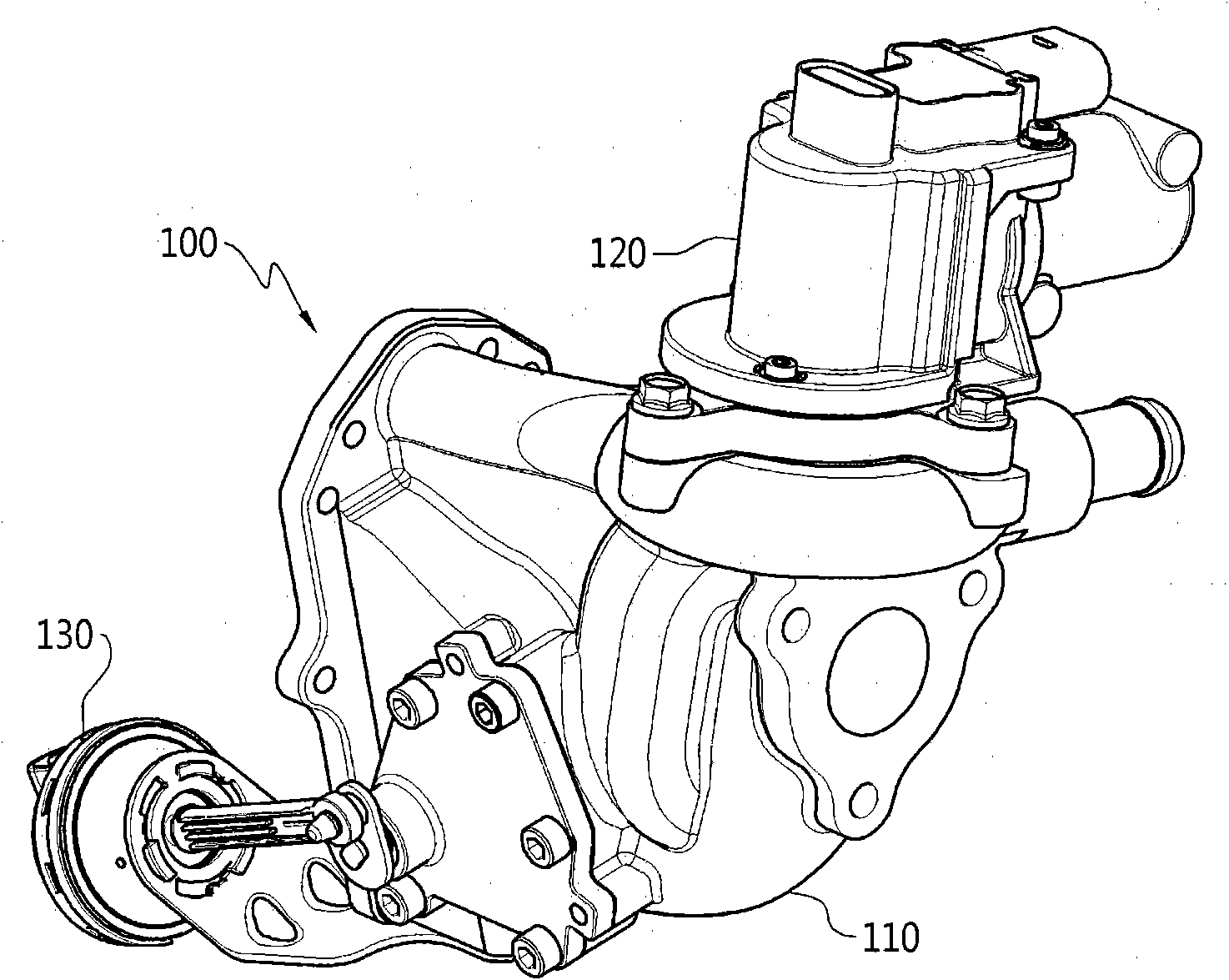
[0050] figure 1 is a diagram of an EGR valve-integrated bypass valve according to an embodiment of the present invention.

[0051] Such as figure 1 As shown, an exhaust gas recirculation valve integrated bypass valve 100 (hereinafter referred to as a bypass valve) according to an embodiment of the present invention includes a valve housing 110, an exhaust gas recirculation valve 120 combined on the valve housing 110, and a The drive unit 130 in front of the valve housing 110 .

[0052]In the bypass valve 100 of this structure, the exhaust gas recirculation valve 120 is combin...


PUM


Abstract

A bypass valve having an EGR valve in which the bypass valve and the EGR valve are assembled into a module is provided. The bypass valve having an EGR valve includes: an intake port formed in a side surface of a valve housing; a first exhaust port formed in another side surface of the valve housing and connected to a cooling flow channel of an EGR cooler; a second exhaust port formed adjacent to the first exhaust port and connected to a bypass flow channel of the EGR cooler; a gas transfer channel formed in the valve housing and having a junction section formed in the middle thereof so as to connect the intake port to the first and second exhaust ports; an EGR valve coupling section formed in the top surface of the valve housing close to the intake port; the EGR valve coupled to the EGR valve coupling section and partially located at a position of the gas transfer channel close to the intake port so as to pass or intercept exhaust gas; and a flap swingably disposed in the junction section so as to selectively open and close the first and second exhaust ports. Since the bypass valve and the EGR valve are assembled into a module, it is advantageous for guaranteeing a space of an engine room at the time of designing a vehicle engine. In addition, the components for connecting the bypass valve and the EGR valve are not necessary, thereby reducing the cost.

Description

technical field [0001] The present invention relates to a bypass valve installed on an exhaust gas recirculation system (Exhaust Gas Recirculation; EGR), in particular to an exhaust gas recirculation valve integrated bypass valve which integrates the bypass valve and the exhaust gas recirculation valve into a module. valve. Background technique [0002] In general, exhaust gas (emisson) is a gas generated when a mixed gas is combusted and discharged to the outside through an exhaust pipe, and includes harmful substances such as carbon monoxide (CO), nitrogen oxides (NOx), and unburned hydrocarbons (HC). [0003] Among the harmful substances contained in these exhaust gases, nitrogen oxides form an inversely proportional causal relationship with carbon monoxide and hydrocarbons. That is, when the fuel is completely combusted and the emissions of carbon monoxide and hydrocarbons are the least, the generation of nitrogen oxides is the greatest. [0004] Therefore, the permitt...

Claims


Application Information

Patent Timeline
Patent Type & Authority Patents(China)
IPC IPC(8): F02M25/07F02N7/08F16K1/18
CPCF02M25/0737F02M25/0729Y02T10/121F02M25/0735F16K1/2007F16K1/20F02M25/0798F02M26/26F02M26/30F02M26/32F02M26/51F02N7/08F16K1/18
Inventor 李昌勋文国灿金炵右金允秀李敬勄李知勇
Owner UNICK
Why Eureka
Try Eureka