Clock synchronization method, system and equipment based on PTP

A clock synchronization and equipment technology, applied in transmission systems, synchronization devices, digital transmission systems, etc., can solve problems such as inaccurate calculation of delay and offset, deviation of sending time, and time-consuming CPU reading registers

Active Publication Date: 2013-12-11
RAISECOM TECH
View PDF3 Cites 4 Cited by
  • Summary
  • Abstract
  • Description
  • Claims
  • Application Information

AI Technical Summary

Problems solved by technology

[0021] In summary, the prior art has the following defects: when the PTP protocol is implemented according to the above method, when the slave clock generates t3, it is realized through an interrupt. The current hardware conditions determine that the interrupt is generated, and the time for the CPU to read the register is relatively short. Time-consuming, so there is a certain deviation between the t3 obtained through the interrupt and the actual sending time of the Delay_Req message, which directly leads to inaccurate calculation of the subsequent delay and offset, thus affecting the clock synchronization accuracy

Method used


Image

  • Clock synchronization method, system and equipment based on PTP
  • Clock synchronization method, system and equipment based on PTP
  • Clock synchronization method, system and equipment based on PTP

Examples


Embodiment Construction

[0050] In order to improve the clock synchronization accuracy of the slave device, an embodiment of the present invention provides a PTP-based clock synchronization method.

[0051] see Figure 5 The PTP-based clock synchronization method provided in the embodiment of the present invention includes the following steps:

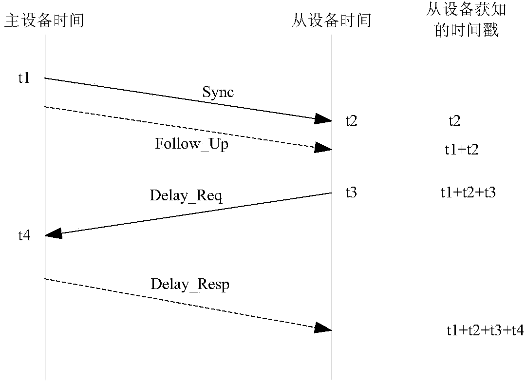
[0052] Step 50: After the slave device receives the synchronization message sent by the master device, record the time point t2 when the synchronization message arrives at the slave device, and read and record the time when the master device sent the synchronization message carried in the synchronization message point t1;

[0053] Step 51: The slave device generates a delay request message, carries the time point t3 of sending the delay request message in the delay request message, and sends the delay request message to the master device;

[0054] Step 52: The slave device receives the delay response message sent by the master device, reads the time point t3...


PUM


Abstract

The embodiment of the invention discloses a clock synchronization method, system and equipment based on a PTP, and relates to the field of wireless communication. The clock synchronization method, system and equipment are used for improving clock synchronization precision of slave equipment. According to the clock synchronization method, system and equipment, after the slave equipment receives synchronization messages sent by master equipment, the time point t2 when the synchronization messages reach the slave equipment is recorded, and a time point t1 when the master equipment carried in the synchronization messages sends synchronization messages is read and recorded; the slave equipment generates delay request messages, enables a time point t3 when the delay request messages are sent to be carried into the delay request messages, and sends the delay request messages to the master equipment; delay response messages sent by the master equipment are received, the time point t3 in the delay response messages and a time point t4 when the delay request messages reach the master equipment are read, and a local clock is regulated according to the time point t1, the time point t2, the time point t3 and the time point t4 to enable the local clock to be synchronized with a clock of the master equipment. By the adoption of the clock synchronization method, system and equipment, clock synchronization precision of the slave equipment can be improved.

Description

technical field [0001] The present invention relates to the field of wireless communication, in particular to a PTP-based clock synchronization method, system and equipment. Background technique [0002] IEEE1588 is a precision clock synchronization protocol standard for network measurement and control systems, referred to as precision time protocol (precision time protocol, PTP). Through the message transmission between the master device and the slave device, the time and frequency offset are calculated, so as to achieve the frequency and time synchronization between the master device and the slave device, and the accuracy can reach the sub-microsecond level. The purpose of this standard is to precisely synchronize measurement and control systems with distributed, independently running clocks. [0003] The basic principle of PTP clock synchronization is as follows: the master device and the slave device exchange messages and record the sending and receiving time of the mes...

Claims


Application Information

Patent Timeline
Patent Type & Authority Applications(China)
IPC IPC(8): H04L7/00
Inventor 郑建威
Owner RAISECOM TECH
Why Eureka
Try Eureka