Two-stage deployment aneurysm embolization devices

An aneurysm, stage technology, applied in medical science, surgery, diagnosis, etc., can solve the problem that the coil is not unfolded, and achieve the effect of promoting interlocking

Active Publication Date: 2013-12-11
TYCO HEALTHCARE GRP LP
View PDF8 Cites 0 Cited by
  • Summary
  • Abstract
  • Description
  • Claims
  • Application Information

AI Technical Summary

Problems solved by technology

However, the coil was not deployed to the designated positio

Method used


Image

  • Two-stage deployment aneurysm embolization devices
  • Two-stage deployment aneurysm embolization devices
  • Two-stage deployment aneurysm embolization devices

Examples


Embodiment Construction

[0025] Several exemplary embodiments of the inventive solution are described below. Reference is made to these examples in a non-limiting manner. These examples are provided to demonstrate the broader applicability of the invention. Various changes may be made and equivalents may be substituted for the subject matter described without departing from the true spirit and scope of the invention.

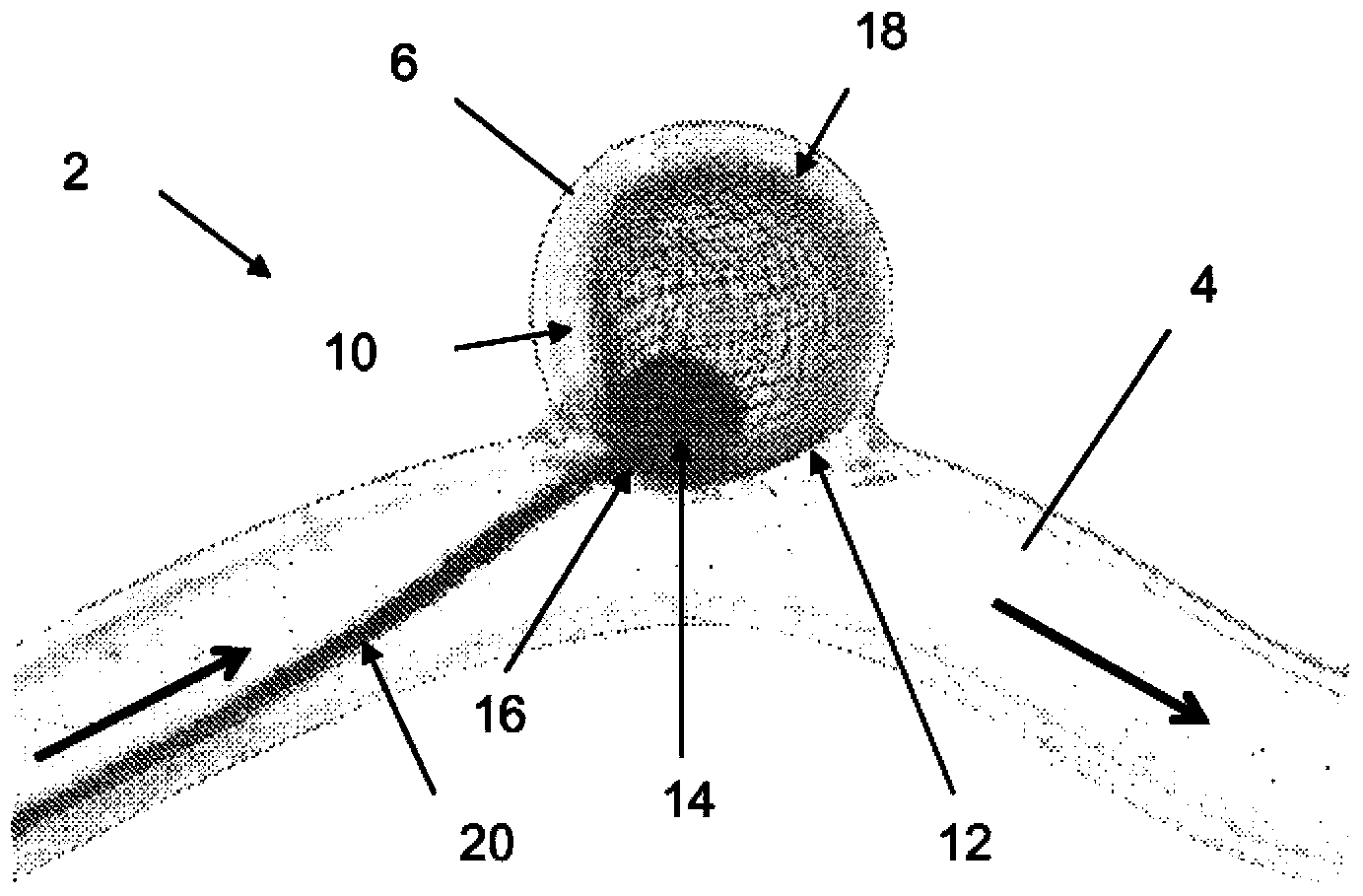
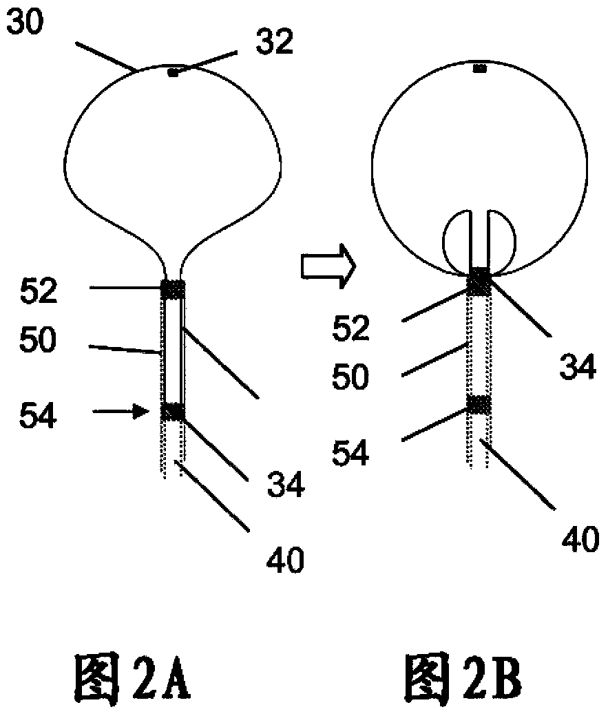
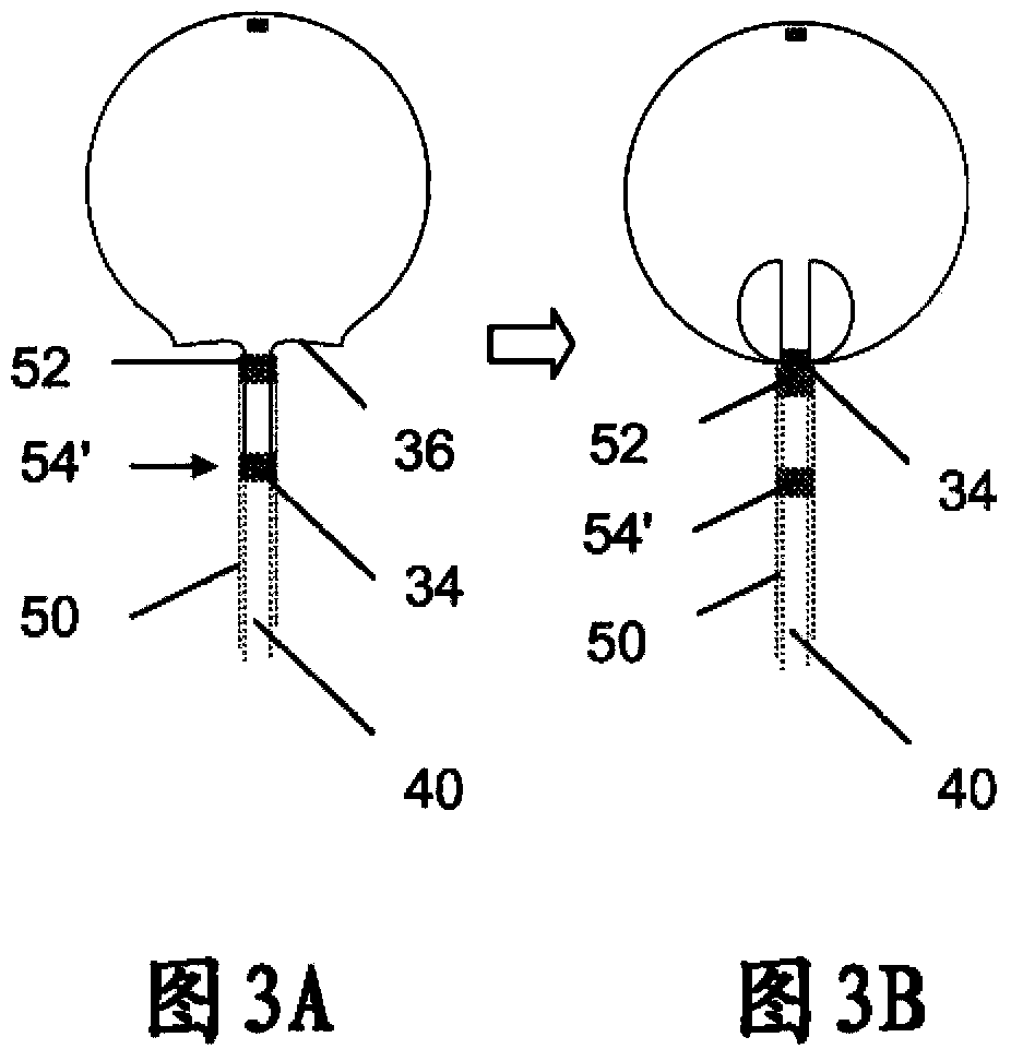
[0026] Aneurysm Embolization System

[0027]The embodiments described herein are specifically designed so that when the implant is deployed to a given stage within the aneurysm, the dimensions of that stage represent the final size and configuration of the implant after final deployment using the delivery system. Several advantages are obtained in conjunction with such a system. One of the advantages is the ability to minimize the delivery profile and / or minimize the complexity of unique implant / delivery system interactions. Another advantage is the larger implant size for a given d...


PUM


Abstract

Embolic implants, delivery systems and methods of manufacture and delivery are disclosed. The subject implants are deployed in two stages. If sized properly as observed in the first stage, they are deployed to the second stage and detached. If not sized properly in/at the first stage, the implants are designed to be withdrawn and replaced with a more appropriately sized implant or another treatment option selected. Some of the implant configurations may be withdrawn even after the second stage deployment as well.

Description

technical field [0001] This application claims priority to US Patent Application No. 61 / 441,845, filed February 11, 2010. Application No. 61 / 441845 and the references cited therein are hereby incorporated by reference in their entirety. Background technique [0002] A number of companies have developed ball-type embolization devices for the treatment of aneurysms. Many of these, including the Nfocus LUNA device and other embodiments disclosed in the co-owned patent application, are designed to fit the size of the implant to a given aneurysm when fully deployed outside the delivery catheter. The same is true for the braid-ball implant disclosed and produced by Sequent Medical, Inc. [0003] With the LUNA device at least, if the dimensions visualized after deployment (under radioactive x-rays, aka "medical imaging") are acceptable to the physician, the implant is detached. If unacceptable, the device is retrieved and replaced with a more suitable size. An example of a devi...

Claims


Application Information

Patent Timeline
IPC IPC(8): A61B17/12
CPCA61B17/12113A61B17/12172A61B2017/00526A61B2017/00867A61B2017/12054A61B2090/0808A61B17/12159
Inventor F·P·贝金S·霍尔登M·S·迪克N·C·德比尔T·瑞瓦拉卡巴A·伦德克维斯特
Owner TYCO HEALTHCARE GRP LP
Why Eureka
Try Eureka