
Rubber belt track iron tooth with trapezoidal guide rail surfaces

A rubber track and guide rail surface technology, applied in the field of track iron teeth, can solve the problems of affecting the service life of the track, falling into the gap, noise, etc., and achieve the effect of reducing track derailment

Inactive Publication Date: 2013-12-18
王文杰
View PDF7 Cites 0 Cited by
  • Summary
  • Abstract
  • Description
  • Claims
  • Application Information

AI Technical Summary

Problems solved by technology

[0002] The rubber crawler under the prior art is generally formed by vulcanizing the iron teeth at equal distances along the annular length direction of the rubber crawler. There must be a certain gap between the two iron teeth. When the supporting wheel is running, the apex of the arc will sink into the gap, which will cause machine vibration and noise. The axial force of the iron teeth will also increase the swing, thus affecting Service life of track

Method used


Image

  • Rubber belt track iron tooth with trapezoidal guide rail surfaces
  • Rubber belt track iron tooth with trapezoidal guide rail surfaces
  • Rubber belt track iron tooth with trapezoidal guide rail surfaces

Examples


Embodiment 1

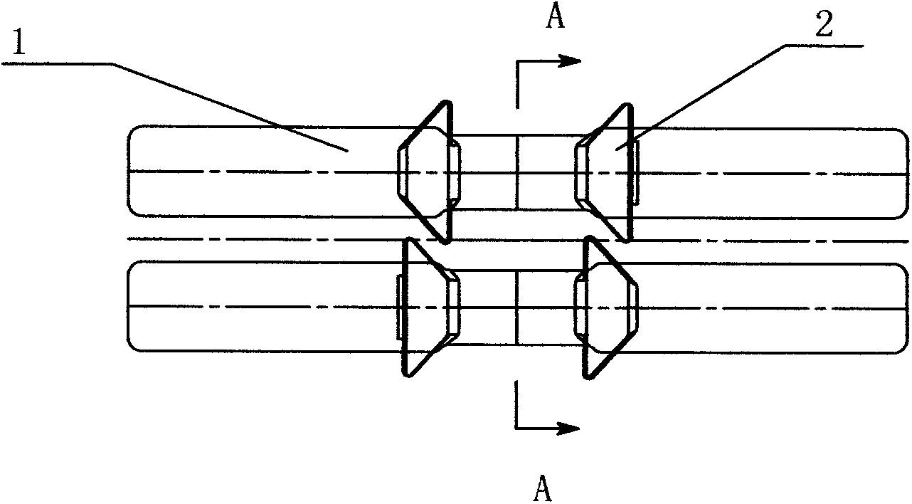
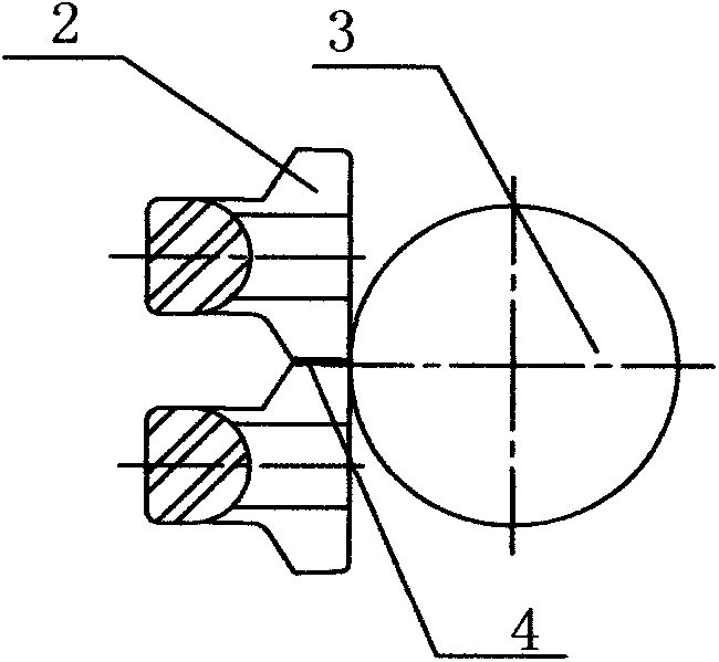
[0016] A rubber crawler iron tooth with a trapezoidal guide rail surface, including an iron tooth body 1, trapezoidal guide rail surfaces 2 in the same direction are arranged on the left and right sides of the iron tooth body 1, and the trapezoidal track surfaces 2 on the upper and lower adjacent sides are in different directions.

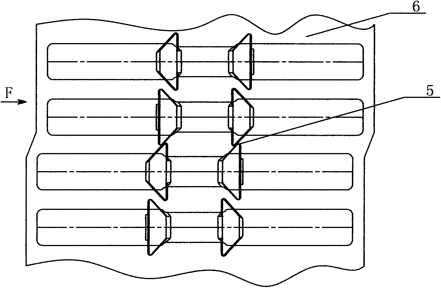
[0017] In this embodiment, the horizontal projections of the trapezoidal track surfaces 2 adjacent to the upper and lower sides have overlapped parts.

[0018] as attached figure 1 , 2 As shown, trapezoidal guide rail surfaces 2 on the left and right sides are formed on the iron tooth body part 1 of the rubber crawler, and the left and right sides are arranged in the same direction, and the upper and lower adjacent trapezoidal guide rail surfaces 2 are arranged in opposite directions, which are laid in the mold in turn and vulcanized with rubber. , the track roller 3 walks on the trapezoidal guide rail surface 2, and the upper and lower adjacent t...


PUM


Abstract

The invention relates to a belt track iron tooth, in particular to a rubber belt track iron tooth with trapezoidal guide rail surfaces. The rubber belt track iron tooth structurally comprises an iron tooth body, wherein synclastic trapezoidal guide rail surfaces are arranged on the left and right sides of the iron tooth body; the trapezoidal guide rail surfaces which are adjacent vertically are different in direction. According to the rubber belt track iron tooth with the trapezoidal guide rail surfaces, the adjacent trapezoidal guide rail surfaces on the iron tooth produce overlapped shadow areas along the profile direction, so that a thrust wheel cannot regularly sink on the guide rail surfaces, and is guaranteed to continuously run from the guide rail surfaces.

Description

technical field [0001] The invention relates to a track iron tooth, in particular to a rubber track iron tooth with a trapezoidal guide rail surface. Background technique [0002] The rubber crawler under the prior art is generally formed by vulcanizing the iron teeth at equal distances along the annular length direction of the rubber crawler. There must be a certain gap between the two iron teeth. When the supporting wheel is running, the apex of the arc will sink into the gap, which will cause machine vibration and noise. The axial force of the iron teeth will also increase the swing, thus affecting service life of the track. Contents of the invention [0003] In order to solve the problems of the prior art, the present invention provides a rubber crawler iron tooth with a trapezoidal guide rail surface. The adjacent trapezoidal guide rail surfaces on the iron teeth produce overlapping shadow areas in the cross-sectional direction, so that the supporting rollers are on ...

Claims


Application Information

Patent Timeline
IPC IPC(8): B62D55/24
Inventor 王文杰
Owner 王文杰
Learn More