Minimally invasive mitral valve retractor

A mitral valve and guide rod technology, applied in the field of medical devices, can solve the problems of cumbersome operation and time-consuming, and achieve the effect of easy operation and storage

Active Publication Date: 2013-12-25
广州市大道医疗科技有限公司
View PDF7 Cites 0 Cited by
  • Summary
  • Abstract
  • Description
  • Claims
  • Application Information

AI Technical Summary

Problems solved by technology

[0003] In the prior art, the fixer fixed on the side of the bed is usually used as the basis for positioning the expansion system to realize the positioning function, but the expansion system in the prior art ca

Method used


Image

  • Minimally invasive mitral valve retractor
  • Minimally invasive mitral valve retractor
  • Minimally invasive mitral valve retractor

Examples


Example Embodiment

[0030] The minimally invasive mitral valve retractor and its operation method provided by the present invention will be described in detail below with reference to the accompanying drawings and specific embodiments.

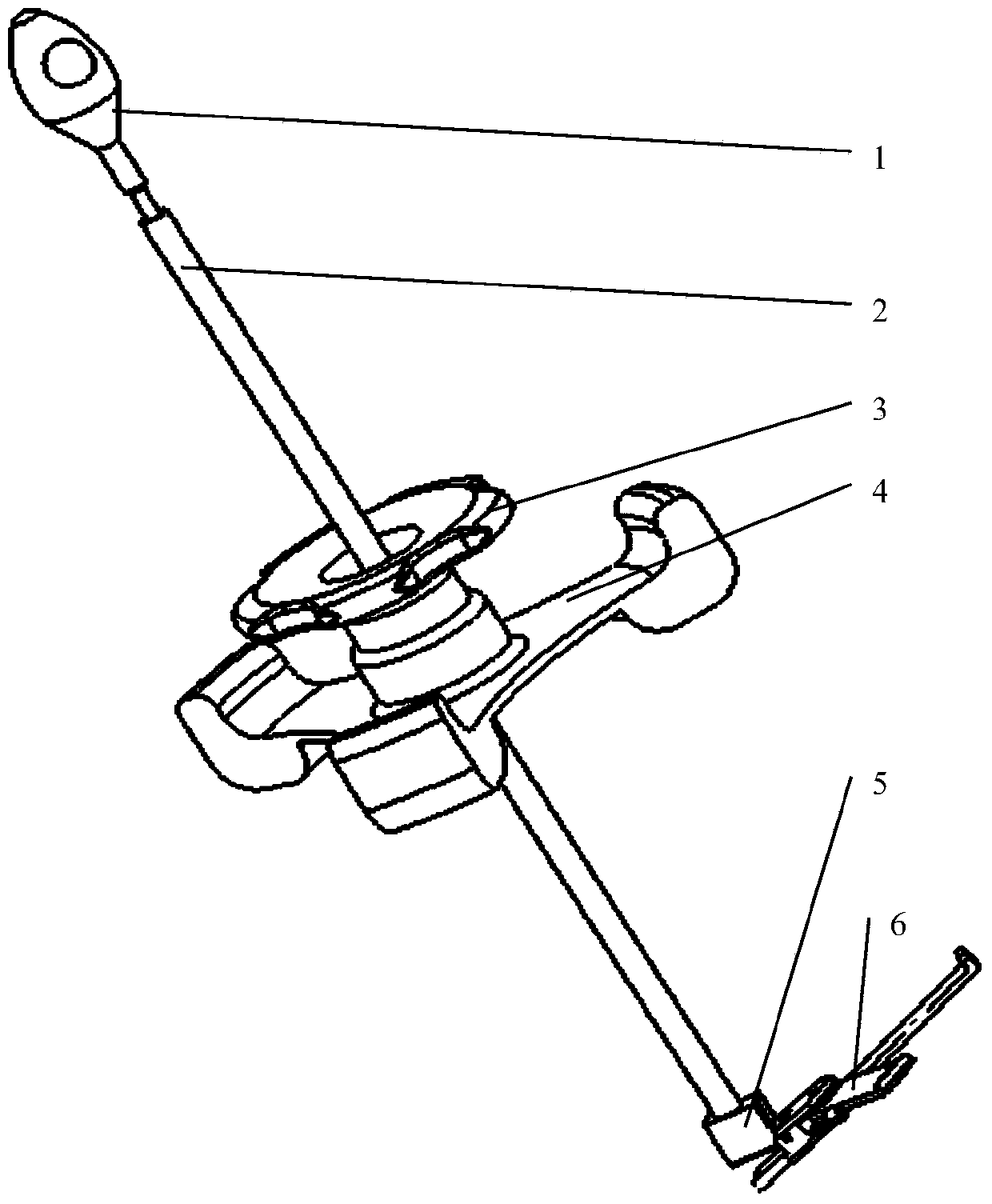
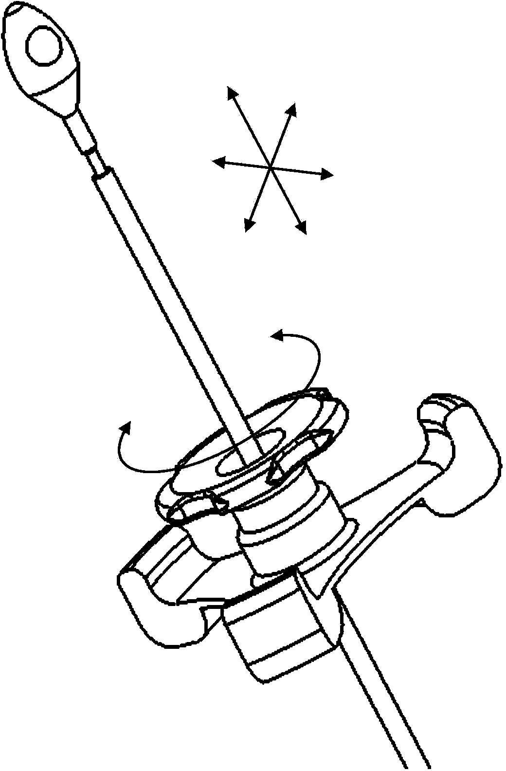
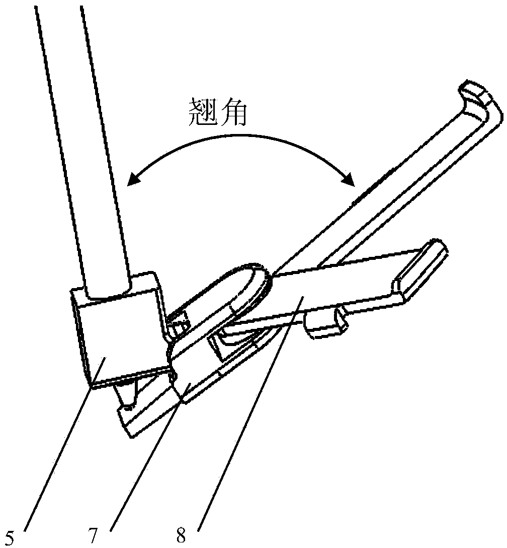
[0031] figure 1 A perspective view of a minimally invasive mitral valve retractor according to an embodiment of the present invention is shown. figure 2 Yes figure 1 An enlarged partial schematic view of the upper half of the minimally invasive mitral valve retractor. image 3 Yes figure 1 An enlarged partial schematic view of the lower half of the minimally invasive mitral valve retractor. Figure 4 Yes figure 1 An exploded perspective view of the guide rod of the minimally invasive mitral valve retractor inserted into the clamping part. Figure 5A Yes figure 1 Top view of the self-adjusting dilator of the minimally invasive mitral valve retractor. Figure 5B Yes figure 1 Side cutaway view of the self-adjusting dilator of the minimally invasive mitral v...


PUM


Abstract

The invention provides a minimally invasive mitral valve reactor comprising a rake-angle adjusting bar (1), a guide bar (2), a fastening portion (5) and a self-positioning expanding unit (6). The rake-angle adjusting bar (1) can be slidably inserted into and pass through the guide bar (2); a through hole is formed in the top of the fastening portion (5), the lower portion of the guide bar (2) is inserted into the through hole of the fastening portion (5) in a fastened manner, and when the rake-angle adjusting bar (1) slides in the guide bar (2), the guide bar (2) is fixed relatively to the fastening portion (5); the lateral side of the fastening portion (5) is pivotally connected with the self-positioning expanding unit (6), so that when the rake-angle adjusting bar (1) is adjusted to drive the fastening portion (5) to pivot, an angle between the guide bar (2) and the self-positioning expanding unit (6) can be adjusted according to the distance that the rake-angle adjusting bar (1) slides in the guide bar (2), and the self-positioning expanding unit (6) is enabled to keep in a position corresponding to the angle.

Description

technical field [0001] The present invention relates to the field of medical devices, and more particularly, to a minimally invasive mitral valve retractor for use in cardiac surgery. Background technique [0002] In cardiac surgery, multiple instruments need to cooperate to complete the operation on a certain operating area. When the operator operates one of the instruments, the other instruments should be stably fixed in a certain position to complete the corresponding auxiliary actions. In order to realize this positioning, a positioning and opening system is generally provided during the operation, and the positioning and opening system can keep a certain designated incision open so as to operate on the tissue inside the incision. [0003] In the prior art, the fixer fixed on the side of the bed is usually used as the basis for positioning the expansion system to realize the positioning function, but the expansion system in the prior art can only have a fixed expansion s...

Claims


Application Information

Patent Timeline
IPC IPC(8): A61B17/02
Inventor 谢斌
Owner 广州市大道医疗科技有限公司
Why Eureka
Try Eureka