Hub shot blasting machine

A technology of shot blasting machine and wheel hub, which is applied in the direction of abrasive jetting machine tools, abrasive materials, metal processing equipment, etc. It can solve problems such as damage to hooks and rollers, limited angle range of shot blasting machine, unreasonable design of shot blasting angle, etc., and achieve reduction Roller table damage, good shot blasting effect, and reasonable installation method

Active Publication Date: 2015-07-15
QINGDAO CHANGJIA MACHINERY
View PDF6 Cites 0 Cited by
  • Summary
  • Abstract
  • Description
  • Claims
  • Application Information

AI Technical Summary

Problems solved by technology

[0002] The existing wheel hub shot blasting machines have hook type and roller table type, but due to the limited angle range of the shot blasting machine, it is easy to cause uneven shot blasting treatment on the surface of the wheel hub, resulting in the part where the product receives the shot blasting treatment can be thrown to the , while the hub in the blind spot of shot blasting is not subject to shot blasting
The hook and the roller table are used as the transmission device of the wheel hub. They work in the shot blasting working environment of the shot blasting machine. Due to the unreasonable design of the shot blasting angle, the thrown projectiles can easily hit the hook and the roller table, causing damage to the hook and the roller table. It affects the service life of the equipment and also affects the shot blasting effect

Method used


Image

  • Hub shot blasting machine
  • Hub shot blasting machine
  • Hub shot blasting machine

Examples


Embodiment 1

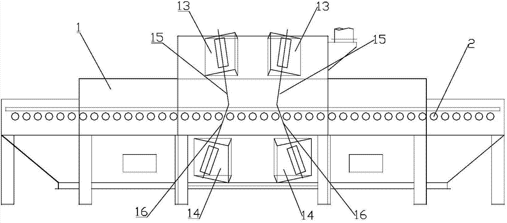
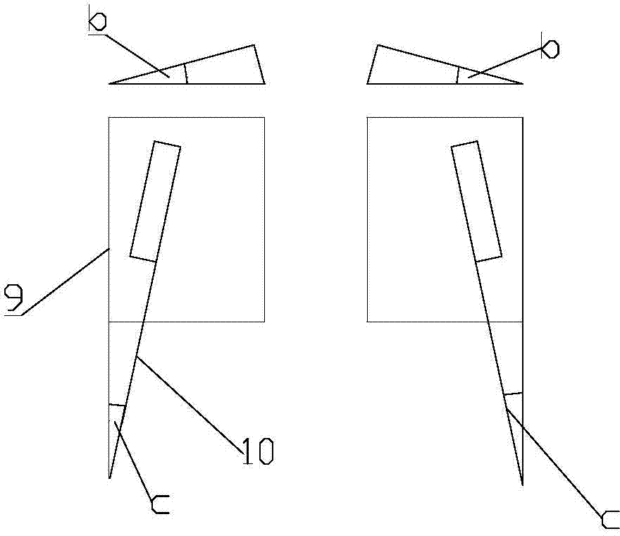
[0016] Such as Figure 1 to Figure 4 as shown, figure 1 It is a schematic diagram of the main structure of the present invention, and at the same time, it also shows the direction angle of the projectile thrown by the shot blaster.

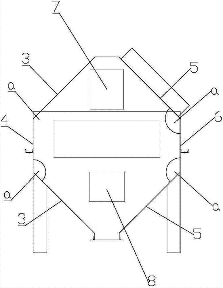
[0017] The hub shot blasting machine includes a frame 1. A cleaning room and a conveying roller table 2 are arranged on the frame 1. The conveying roller table 2 passes through the cleaning room. The conveying roller table 2 is composed of a plurality of conveying rollers. Two adjacent conveying rollers The distance between them is l, and the range of the distance l is 170mm; the cleaning chamber is divided into upper cleaning chamber 7 and lower cleaning chamber 8 by the conveying roller table. 8 The left and right side walls are composed of two parts, the left vertical wall 4 and the left inclined wall 3, the right vertical wall 6 and the right inclined wall 5; the left vertical wall 4 and the left inclined wall 3 form an angle a, and the angle...

Embodiment 2

[0021] The hub shot blasting machine includes a frame 1. A cleaning room and a conveying roller table 2 are arranged on the frame 1. The conveying roller table 2 passes through the cleaning room. The conveying roller table 2 is composed of a plurality of conveying rollers. Two adjacent conveying rollers The distance between them is 1, and the range of the distance 1 is 175mm; the cleaning chamber is divided into upper cleaning chamber 7 and lower cleaning chamber 8 by the conveying roller table. 8 The left and right side walls are composed of two parts, the left vertical wall 4 and the left inclined wall 3, the right vertical wall 6 and the right inclined wall 5; the left vertical wall 4 and the left inclined wall 3 form an angle a, and the angle a is 130 degree angle, the right vertical wall 6 and the right inclined wall 5 form an included angle and also form an angle a, and the angle a is an angle of 130 degrees.

[0022] The cleaning room is provided with a shot blasting ma...

Embodiment 3

[0025] The hub shot blasting machine includes a frame 1. A cleaning room and a conveying roller table 2 are arranged on the frame 1. The conveying roller table 2 passes through the cleaning room. The conveying roller table 2 is composed of a plurality of conveying rollers. Two adjacent conveying rollers The distance between them is l, and the range of distance l is 180mm; the cleaning room is divided into upper cleaning room 7 and lower cleaning room 8 by the conveying roller table. 8 The left and right side walls are composed of two parts, the left vertical wall 4 and the left inclined wall 3, the right vertical wall 6 and the right inclined wall 5; the left vertical wall 4 and the left inclined wall 3 form an angle a, and the angle a is 133 degree angle, the right vertical wall 6 and the right inclined wall 5 form an included angle and also form an angle a, and the angle a is an angle of 133 degrees.

[0026] The cleaning room is provided with a shot blasting machine seat, a...


PUM


Abstract

The invention relates to a hub shot blasting machine. The hub shot blasting machine comprises a stander, wherein a cleaning chamber and a conveying roller bed are arranged on the stander, and the conveying roller bed penetrates through the cleaning chamber. The hub shot blasting machine is characterized in that the conveying roller bed consists of a plurality of conveying rollers, wherein the distance between each two conveying rollers is l, and the range of the l is 170-185mm; the cleaning chamber is divided into an upper cleaning chamber and a lower cleaning chamber by the conveying roller bed, and both the left and right side walls of the upper cleaning chamber and the lower cleaning chamber consist of two parts when being seen from the advancing direction of the conveying roller bed, namely a left vertical wall, a left slant wall, a right vertical wall and a right slant wall; the left vertical wall and the left slant wall form an included angle a, the right vertical wall and the right slant wall form an included angle a as well, and the range of the included angle is 125-145 degrees; two upper impeller heads are respectively arranged on the left slant wall and right slant wall of the upper cleaning chamber, and two lower impeller heads are respectively arranged on the left slant wall and right slant wall of the lower cleaning chamber. The hub shot blasting machine is reasonable in structure, comprehensive in angles of the impeller heads, high in working efficiency and good in shot blasting effect.

Description

technical field [0001] The invention belongs to the technical field of shot blasting machines, and relates to a shot blasting machine, in particular to a wheel hub shot blasting machine for performing shot blasting on wheel hubs. Background technique [0002] The existing wheel hub shot blasting machines have hook type and roller table type, but due to the limited angle range of the shot blasting machine, it is easy to cause uneven shot blasting treatment on the surface of the wheel hub, resulting in the part where the product receives the shot blasting treatment can be thrown to , and the wheel hub in the blind spot of shot blasting is not subject to shot blasting. The hook and roller table are used as the transmission device of the wheel hub. They work in the shot blasting working environment of the shot blasting machine. Due to the unreasonable design of the shot blasting angle, the thrown projectiles can easily hit the hook and roller table, causing damage to the hook an...

Claims


Application Information

Patent Timeline
Patent Type & Authority Patents(China)
IPC IPC(8): B24C3/14
Inventor 王风刚刘胜昌巩学良张继春丁万成
Owner QINGDAO CHANGJIA MACHINERY
Why Eureka
Try Eureka