Rotation type demolding mechanism for J-shaped drain trap

The technology of a demoulding mechanism and water trap, which is applied in the field of J-shaped water trap rotary demoulding mechanism, can solve the problems of high labor intensity, low production efficiency and high labor cost.

Inactive Publication Date: 2013-12-25
TAIZHOU HUANGYAN WEIDA PLASTIC MACHINERY
View PDF7 Cites 4 Cited by
  • Summary
  • Abstract
  • Description
  • Claims
  • Application Information

AI Technical Summary

Problems solved by technology

However, there is a big problem with the structure of the mold. Since the diameter of the J-shaped trap is small, and the distance between the two diameters is very close to each other, when the direct-drawing mechanism and the rotary core-pulling mechanism are installed in the mold, the direct-drawing mechanism will The rotary core-pulling mechanism is blocked, so that the rotary core-pull

Method used


Image

  • Rotation type demolding mechanism for J-shaped drain trap
  • Rotation type demolding mechanism for J-shaped drain trap
  • Rotation type demolding mechanism for J-shaped drain trap

Examples


Embodiment Construction

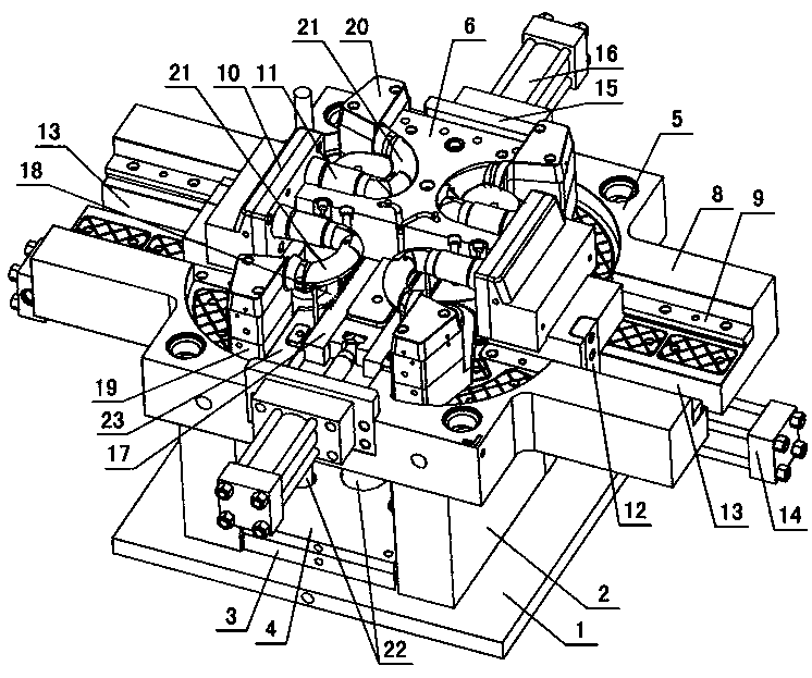
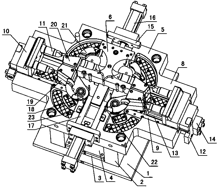
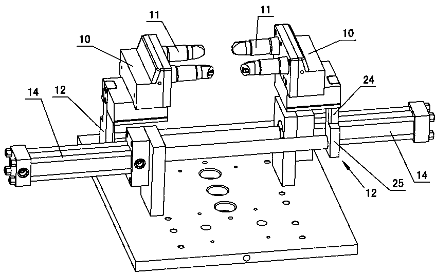
[0012] The invention relates to a J-shaped water trap rotary demoulding mechanism, such as figure 1 — Figure 5 As shown, it includes the lower doubler plate 1, the mold foot 2 is installed on the lower doubler plate, the thimble base plate 3 and the thimble panel 4 are arranged between the mold feet, the ejector rod 22 is installed between the thimble base plate and the thimble panel, and the movable mold is installed on the mold foot Frame 5, the movable mold cavity 6 is installed on the movable mold frame, there is a fixed mold cavity on the movable mold cavity, there are cores in the fixed mold cavity and the dynamic mold cavity, and there is injection molding between the fixed mold cavity, the dynamic mold cavity and the core. The J-shaped trap 7 is characterized in that: the left and right sides of the movable mold frame 5 are shaped with growth-type left and right slides 8, the growth-type left and right slides are equipped with left and right beading bars 9, and the le...


PUM


Abstract

The invention relates to a rotation type demolding mechanism for a J-shaped drain trap. The mechanism comprises a lower compound plate, wherein mold feet are mounted on the lower compound plate, a thimble base plate and a thimble panel are arranged among the mold feet, and an ejector rod is mounted between the thimble base plate and the thimble panel; a movable mold frame is mounted on the mold feet, a movable model cavity is formed in the movable mold frame, a fixed model cavity is formed in the movable model cavity, mold cores are arranged in the model cavities, and J-shaped drain traps are arranged among the model cavities and the mold cores in an injection molding manner. The mechanism is characterized in that left and right lengthened type chutes are respectively arranged on the left and right sides of the movable mold frame, and left and right depression bars are respectively arranged on the left and right chutes; left and right sliding block seats are arranged among the left and right depression bars, and the left and right chutes, and straightly-drawn mold cores are mounted on the left and right sliding block seats; connecting plates are mounted below the left and right sliding block seats; guide troughs are formed in the left and right lengthened type chutes and are matched with the connecting plates; a reverse-pushing oil cylinder is mounted below the left and right lengthened type chutes; fixed plates are mounted on the front and rear sides of the movable mold frame, and front and rear oil cylinders are mounted on the fixed plates and are connected with racks; rotating gears are mounted in the movable mold frame and are meshed with the racks; rotating plates are arranged on the rotating gears, rotating mold core sliding blocks are mounted on the rotating plates, and rotating mold cores are mounted on the rotating mold core sliding blocks and are matched with bent pipe parts of the J-shaped drain traps.

Description

technical field [0001] The invention relates to a demoulding mechanism for a water trap, in particular to a rotary type demoulding mechanism for a J-shaped water trap. Background technique [0002] J-shaped elbow pipe fitting is a commonly used water trap pipe fitting. A certain amount of water can be kept in the water trap pipe fitting to isolate the air under the sewer from the indoor air, preventing odor and small insects from entering the room, which is harmful to people's life. Levels and physical fitness have helped a lot. However, there is a big problem with the structure of the mold. Since the diameter of the J-shaped trap is small, and the distance between the two diameters is very close to each other, when the direct-drawing mechanism and the rotary core-pulling mechanism are installed in the mold, the direct-drawing mechanism will The rotary core-pulling mechanism is blocked, so that the rotary core-pulling mechanism has no place to pull the core. Most of the ex...

Claims


Application Information

Patent Timeline
IPC IPC(8): B29C45/40
Inventor 张欢庆
Owner TAIZHOU HUANGYAN WEIDA PLASTIC MACHINERY
Why Eureka
Try Eureka