Bidirectional electromagnetic diaphragm pump

A diaphragm pump and electromagnetic technology, applied in the direction of pumps, pumps with flexible working elements, liquid variable capacity machinery, etc., can solve the problems of small flow, large flow pulsation, and low pump efficiency of electromagnetic diaphragm pumps, and achieve continuous flow, High operating efficiency and easy maintenance

Active Publication Date: 2013-12-25
JIANGSU UNIV
View PDF8 Cites 5 Cited by
  • Summary
  • Abstract
  • Description
  • Claims
  • Application Information

AI Technical Summary

Problems solved by technology

[0005] The technical problem to be solved by the present invention is that the electromagnetic diaphragm pump has the defects of small flow rate, large flow pulsation and low pump efficiency. A bid

Method used


Image

  • Bidirectional electromagnetic diaphragm pump
  • Bidirectional electromagnetic diaphragm pump
  • Bidirectional electromagnetic diaphragm pump

Examples


Embodiment Construction

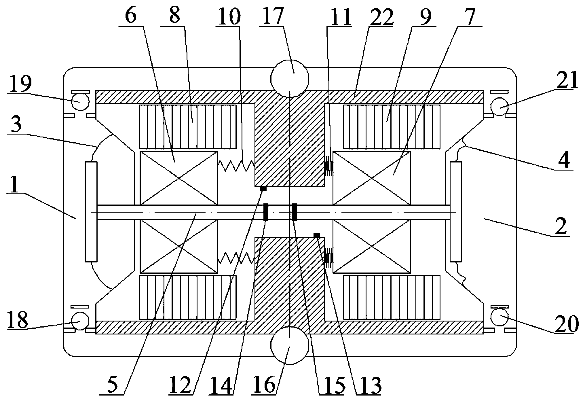
[0016] combine figure 1 , a bidirectional electromagnetic diaphragm pump according to the present invention, including basic components such as pump head, check valve, diaphragm, pump shaft, armature, coil, spring, pump casing, etc. Permanent magnets and Hall sensors. Pump head A, pump head B, and pump casing are located in a hollow cuboid structure composed of pump head A and pump head B. The four corners of the hollow structure are equipped with check valves A, A, One-way valve B, one-way valve C, one-way valve D, the pump casing is composed of two convex structures, one convex body has an inlet in the center of the bottom, and the other convex body has an outlet in the center of the bottom, and the middle of the two convex structures The pump shaft, the diaphragm A and the diaphragm B are connected at both ends of the pump shaft, the armature A and the armature B are symmetrically fixed on the pump shaft, the coil A and the coil B are respectively between the armature A, t...


PUM


Abstract

The invention discloses a bidirectional electromagnetic diaphragm pump which relates to the technical field of electromagnetic diaphragm pump manufacturing; a diaphragm A and a diaphragm B are connected on both ends of a pump shaft; an armature A and an armature B are symmetrically fixed on the pump shaft; a coil A and a coil B are respectively sleeved outside the armature A and the armature B; a spring A and a spring B are respectively connected on a pump shell and the armatures A and B; a Hall sensor A and a Hall sensor B are symmetrically fixed on the pump shell and are towards the pump shaft; an annular permanent magnet A and an annular permanent magnet B are symmetrically fixed at the middle part of the pump shaft, and between the axial positions of the Hall sensor A and the Hall sensor B; the coil A and the coil B are electrified and produce magnetic force; when the Hall sensors A and B respectively sense with the annular permanent magnets A and B, the electrification directions of the coils are reverse, and the pump shaft is driven to suction and drain liquid back and forth and left and right. According to the bidirectional electromagnetic diaphragm pump, the flow of the pump can be increased by suctioning and draining liquid with double pump heads in sequence, the double pump heads suction and drain liquid alternatively and the flow pulsation can be reduced, and the efficiency of the pump can be improved by driving with the bidirectional electromagnet instead of a motor.

Description

technical field [0001] The invention belongs to the technical field of electromagnetic diaphragm pump manufacturing, in particular to the field of a bidirectional electromagnetic diaphragm pump. Background technique [0002] The current types of diaphragm pumps can be divided into pneumatic diaphragm pumps powered by compressed air, hydraulic diaphragm pumps powered by hydraulic oil medium, and electric diaphragm pumps powered by electricity. Among them, pneumatic diaphragm pumps and hydraulic diaphragm pumps need attached air compressors and hydraulic pumps and other devices, which are large in size and limit the installation space; electric diaphragm pumps can be divided into motor-driven diaphragm pumps and electromagnet-driven metering pumps. , The motor-driven electric diaphragm pump has complex structure, low mechanical efficiency, and is easily affected by power supply voltage and frequency. The electromagnet-driven diaphragm pump replaces the motor part with an elect...

Claims


Application Information

Patent Timeline
IPC IPC(8): F04B43/04
Inventor 刘厚林崔建保谈明高王勇周孝华丁剑
Owner JIANGSU UNIV
Why Eureka
Try Eureka