Mechanical fixed connecting block

A technology for mechanical fixing and connecting blocks, applied in the field of mechanical parts

Inactive Publication Date: 2013-12-25
SUZHOU BODENA TECH
View PDF7 Cites 1 Cited by
  • Summary
  • Abstract
  • Description
  • Claims
  • Application Information

AI Technical Summary

Problems solved by technology

However, the existing machinery cannot provide a mechanically fixed connection block that connects the shaft-shaped part with other parts and provides a matching space and a limit function for other mechanical parts.

Method used


Image

  • Mechanical fixed connecting block
  • Mechanical fixed connecting block

Examples


Embodiment Construction

[0014] The present invention will be specifically introduced below in conjunction with the accompanying drawings and specific embodiments.

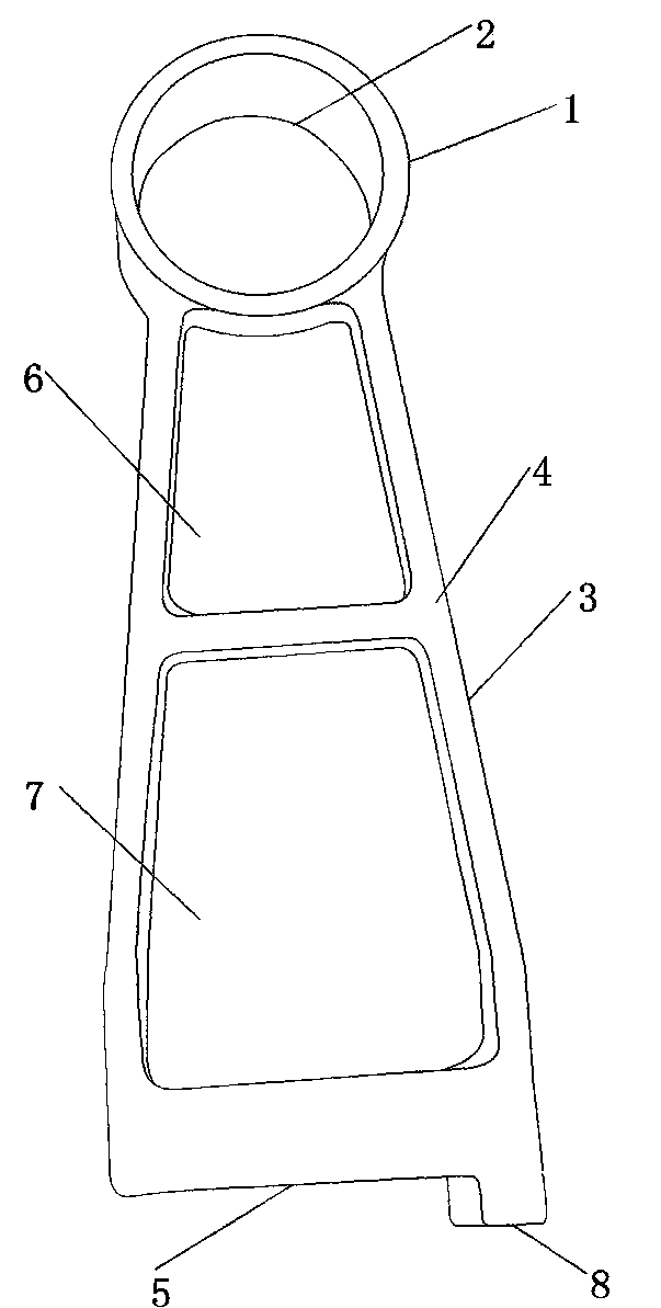
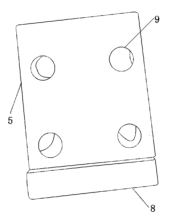
[0015] refer to figure 1 As shown, a mechanically fixed connection block of the present invention includes: a fixed block 1 and a connecting plate 3 connected to the fixed block 1; a circular through hole 2 is provided on the fixed block 1, and the connecting plate 3 includes a first side 4 and a second Two sides 5 , the first side 4 is provided with a first groove 6 and the second groove 7 , the second side 5 is provided with a plurality of threaded holes 9 , and the second side 5 is provided with a boss 8 . The shaft-shaped part passes through the circular through hole 2, and other parts are connected with the second side 5 through the threaded hole 9, thereby connecting the shaft-shaped part with other parts. The first groove 6 and the second groove 7 provide matching space for other mechanical parts, and the boss 8 is used to limit t...


PUM

PropertyMeasurementUnit
Apertureaaaaaaaaaa

Abstract

The invention discloses a mechanical fixed connecting block, which is characterized by comprising a fixing block and a connecting plate connected with the fixing block, wherein a round through hole is formed in the fixing block; the connecting plate comprises a first lateral surface and a second lateral surface; a first groove and a second groove are formed in the first lateral surface; a plurality of threaded holes are formed in the second lateral surface; a lug boss is arranged on the second lateral surface. According to the mechanical fixed connecting block, a shaft-shaped part can be connected with other parts, a matching space can be provided for other mechanical parts, and a limiting function can be realized.

Description

technical field [0001] The invention relates to a mechanical part, in particular to a mechanically fixed connection block for connecting a shaft-shaped part with other parts. Background technique [0002] In all kinds of mechanical equipment, connecting and installing parts are widely used. There are also many shapes and structures of these mechanical connection and installation parts, and the materials and processing techniques used are also different. However, the existing machinery cannot provide a mechanically fixed connection block that connects the shaft-shaped component with other components and provides a matching space and a position-limiting function for other mechanical components. Contents of the invention [0003] In order to solve the deficiencies of the prior art, the object of the present invention is to provide a mechanically fixed connection block. [0004] In order to achieve the above object, the present invention adopts the following technical soluti...

Claims


Application Information

Patent Timeline
IPC IPC(8): F16B1/00
Inventor 黄志刚
Owner SUZHOU BODENA TECH
Why Eureka
Try Eureka