
Manufacturing method of force sensing resonant element

A technology of resonant components and manufacturing methods, which is applied in the field of sensors, can solve problems such as vibration beam excitation amplitude drop, low electrode excitation efficiency, and poor stability, and achieve the effects of improved excitation efficiency, good consistency, and short distance

Active Publication Date: 2015-06-10
CHINA ELECTRONICS TECH GRP NO 26 RES INST
View PDF5 Cites 0 Cited by
  • Summary
  • Abstract
  • Description
  • Claims
  • Application Information

AI Technical Summary

Problems solved by technology

This patent designs a pressure sensor that uses a rectangular cross-section and double vibrating beams vibrating in opposite directions as the resonant element, which is more suitable for low-cost mass production using micromachining technology, but the resonant beam adopts a rectangular cross-section structure, and the excitation efficiency of the electrodes is low. Low, with the further reduction of the component size, the excitation vibration amplitude of the vibrating beam will also decrease, and the stability will deteriorate

Method used


Image

  • Manufacturing method of force sensing resonant element
  • Manufacturing method of force sensing resonant element
  • Manufacturing method of force sensing resonant element

Examples


Embodiment 1

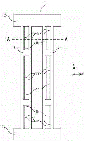
[0035] Such as Figure 1a and Figure 1b As shown, a force-sensitive resonant element 1 includes two bases 2 arranged in parallel up and down, and two resonant beams 3 operating in the width bending resonance mode are arranged in parallel and symmetrically between the two bases 2, and the resonant beams The front and back surfaces of 3 are respectively provided with three grooves-the end grooves at both ends and the middle groove between the end grooves. The inner wall of the groove and the two side walls of the resonant beam are respectively covered with electrodes for connecting the excitation power supply. The opening direction of the groove is perpendicular to the vibration direction of the resonant beam, and the two resonant beams are set to vibrate through the direction of the excitation power supply. in the opposite direction. Each end groove is made of two parallel end deep grooves 4a and an end shallow groove 4b between the two end deep grooves and connected with the...

Embodiment 2

[0043] Such as Figure 2a and Figure 2b As shown, the structure of the force-sensitive resonant element of this embodiment is similar to that of embodiment 1, the difference is that the resonant beam 3 is only provided with grooves on one of the front and rear surfaces. To highlight the shape of the cross-section, Figure 2b Electrodes are not shown.

[0044] For thinner resonant beams, when the grooves are made on both sides at the same time, the deep grooves 4a at the end and the deep grooves 5a in the middle are easy to etch through, which reduces the dynamic strength of the resonant beam 3, while the resonant beam 3 resonates. The dynamic impedance will increase, reducing the stability of the force-sensitive resonant element. The structure of the resonant beam 3 with grooves formed on one side in this embodiment is more suitable for the manufacture of a force-sensitive resonant element 1 that is miniaturized and based on a thinner substrate.

Embodiment 3

[0046] Such as Figure 3a and Figure 3b As shown, the force-sensitive resonant element of this embodiment is similar in structure to the force-sensitive resonant element of embodiment 1, the difference is that the middle groove (including the middle shallow groove 5b and the middle deep groove 5a) is not set on the two resonant beams. ). To highlight the shape of the cross-section, Figure 3b Electrodes are not shown.

[0047] When the length of the resonant beam 3 is further shortened, if the front and back sides of the resonant beam 3 are made with a central groove at the same time, the difficulty of electrode patterning on the surface will increase, and the probability of short-circuiting between the first electrode 6a and the second electrode 6b will increase. Both yield and reliability of component fabrication are reduced. The structure of the resonant beam 3 in this embodiment is more suitable for the manufacture of a force-sensitive resonant element with a shorter ...


PUM


Abstract

The invention discloses a force sensing resonant element and a manufacturing method thereof. The force sensing resonant element comprises two bases and two resonant beams, wherein at least one of the front side and the back side of each resonant beam is provided with grooves, the inner wall of each groove and the lateral wall of each resonant beam are respectively covered by an electrode, the vibration directions of the two resonant beams are opposite through the setting of the direction of an excitation power supply, the grooves in each side of each resonant beam at least relate to end grooves located in the two ends of the resonant beam, and each end groove is composed of two end deep groove bodies which are arranged in two sides in parallel and an end shallow groove body located between the two end deep groove bodies and connected with the two end deep groove bodies into a whole. According to the force sensing resonant element, the distance between acting surfaces of the electrodes is short, the field intensity in the resonant beams is increased, the excitation efficiency of the electrodes is improved, and therefore the force sensing resonant element is more suitable for microminiaturization manufacturing of sensors; the deep groove bodies are formed, the steep degree of the lateral wall of each groove is increased, therefore, the excitation efficiency of the electrodes is improved, and the excitation efficiency of the resonant beams is improved.

Description

technical field [0001] The invention relates to the technical field of sensors, in particular to a force-sensitive resonant element applied to a micro-mechanical sensor and a manufacturing method of the force-sensitive resonant element. Background technique [0002] As a sensor for detecting mechanical parameters, micromechanical sensors have been widely used in many fields. According to different detection principles, mechanical sensors can be divided into capacitive, piezoresistive, resonant and other types, among which the resonant type has high sensitivity and frequency output, and can be directly connected to digital circuits for signal processing without modulus Signal conversion has become an important research direction at present. The force-sensitive resonant element is the sensitive element of the resonant mechanical sensor and the core component of the resonant mechanical sensor. Its structure and parameters will directly affect the overall performance of the sen...

Claims


Application Information

Patent Timeline
Patent Type & Authority Patents(China)
IPC IPC(8): G01L9/00G01L1/00G01L23/08B81C1/00
Inventor 林丙涛赵建华董宏奎
Owner CHINA ELECTRONICS TECH GRP NO 26 RES INST
Learn More