Quartz resonant element

A technology of resonant components and quartz, which is applied in the field of resonators, can solve problems such as poor symmetry, limited increase in electric field strength, and low resonance stability of resonant components, and achieve the effects of enhanced stability, increased field strength, and improved excitation efficiency

Active Publication Date: 2016-06-08
CHINA ELECTRONICS TECH GRP NO 26 RES INST
View PDF5 Cites 0 Cited by
  • Summary
  • Abstract
  • Description
  • Claims
  • Application Information

AI Technical Summary

Problems solved by technology

However, due to the anisotropy of the quartz crystal, the steepness of the side wall in the +X direction of the groove and the poor symmetry of the left and right ends of a single resonant beam, the increase in the electric field strength is limited, and the resonance stability of the resonant element is not high.

Method used


Image

  • Quartz resonant element
  • Quartz resonant element
  • Quartz resonant element

Examples


Embodiment 1

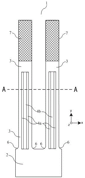
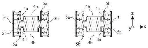
[0019] like Figure 1a and Figure 1b As shown, the quartz resonant element 1 of the present invention includes a base 2 for mounting and fixing and two resonant beams 3, which are arranged parallel and symmetrically along the Y direction and work in a width bending resonant mode. One end of the two resonant beams 3 is connected to the base 2 , and chamfers 6 are provided on the left and right sides of the resonant beams connected to the base to smoothly connect with the base, so as to improve the reliability of the quartz resonant element 1 . The front and rear surfaces of the resonant beam 3 are respectively provided with symmetrical grooves, and the opening direction of the grooves is perpendicular to the vibration direction of the resonant beam. The grooves are composed of deep grooves 4a parallel on both sides and shallow grooves 4b located between the two deep grooves 4a and integrated with the two deep grooves. The inner wall of the groove and the two side walls of the...

Embodiment 2

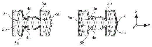
[0026] like Figure 2a and Figure 2b As shown, the structure of the quartz resonant element of this embodiment is similar to the structure of the quartz resonant element of embodiment 1, the difference is that the resonant beam 3 is only provided with grooves on one of the front and rear surfaces. To highlight the shape of the surface grooves, Figure 2a Electrodes are not shown.

[0027] For thinner resonant beams, when the grooves are made on both sides at the same time, the deep groove 4a is easy to etch through, which reduces the dynamic strength of the resonant beam 3. At the same time, the dynamic impedance of the resonant beam 3 will increase when it resonates, reducing the quartz Stability of the resonant element. The structure of the resonant beam 3 with grooves formed on one side in this embodiment is more suitable for the manufacture of a miniaturized quartz resonant element 1 based on a thinner substrate. Since the groove is set on one side, the metal mass blo...


PUM


Abstract

The invention discloses a quartz resonant element, which comprises a base and two resonant beams, at least one of the front and back sides of the resonant beam is provided with a groove, and the groove is composed of parallel deep grooves on both sides and two deep grooves A shallow groove is formed between the grooves and connected with two deep grooves. The inner wall of the groove and the two side walls of the resonant beam are respectively covered with electrodes, and the two resonant beams are connected with different polarities of the excitation power to make their vibration directions opposite. The quartz resonant element is provided with a deep groove, which increases the steepness of the side wall of the groove, shortens the action distance between the exciting electrode pairs, increases the field strength in the resonant beam, and improves the excitation efficiency of the electrodes. It is suitable for resonators. Miniaturization. In addition, after the deep groove is set, the symmetry of the left and right ends of a single resonant beam is effectively improved, the left and right resonant beams vibrate in opposite directions, and the resonance stability of the resonant element is enhanced.

Description

technical field [0001] The invention relates to the technical field of resonators, in particular to a quartz resonant element applied to micro-resonators. Background technique [0002] As a device that outputs a fixed frequency, a microresonator has been widely used in many fields. The resonant element is the core component of the resonator, and its size and performance will directly determine the size and performance of the resonator. Quartz crystal has high quality factor, good temperature stability, and can be processed by micro-machining technology. It is often used as the base material of high-stability resonant components. With the continuous reduction of the volume of the quartz resonant element, the dynamic impedance value during resonance also increases, the stability decreases, and the power consumption increases. [0003] In order to reduce the dynamic impedance value of the quartz resonant element and improve the resonance efficiency, the U.S. patent "Resonator...

Claims


Application Information

Patent Timeline
Patent Type & Authority Patents(China)
IPC IPC(8): H03H9/02H03H9/19
Inventor 林丙涛林日乐班亚娟赵建华
Owner CHINA ELECTRONICS TECH GRP NO 26 RES INST
Why Eureka
Try Eureka