Hardware plug foot bending mechanism and bending method

A bending mechanism and hardware technology, applied in metal processing equipment, forming tools, manufacturing tools, etc., can solve the problems of high cost of machinery and equipment, long time required for bending, low bending efficiency, etc., to reduce the cost of machinery and equipment The effect of reducing cost, shortening bending time, and improving efficiency

Inactive Publication Date: 2014-01-01
DONGGUAN GOOD MARK NEW PRECISION TECH CO LTD
View PDF5 Cites 2 Cited by
  • Summary
  • Abstract
  • Description
  • Claims
  • Application Information

AI Technical Summary

Problems solved by technology

[0003] The completion process of the hardware 1 in the above-mentioned prior art requires two operating mechanisms and two processes to complete. Firstly, the two operating mechanisms lead to high cost of machinery and equipment. Secondly, there are two processes, which take a long time to bend, and the bending The efficiency is low, and the flattening mechanism in the second process needs to reposition the pin 11 accurately before applying force, which is more complicated

Method used


Image

  • Hardware plug foot bending mechanism and bending method
  • Hardware plug foot bending mechanism and bending method
  • Hardware plug foot bending mechanism and bending method

Examples


Embodiment Construction

[0027] The present application is further described in conjunction with the following examples.

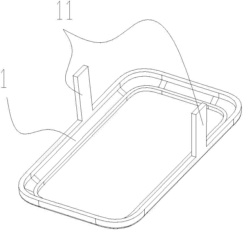
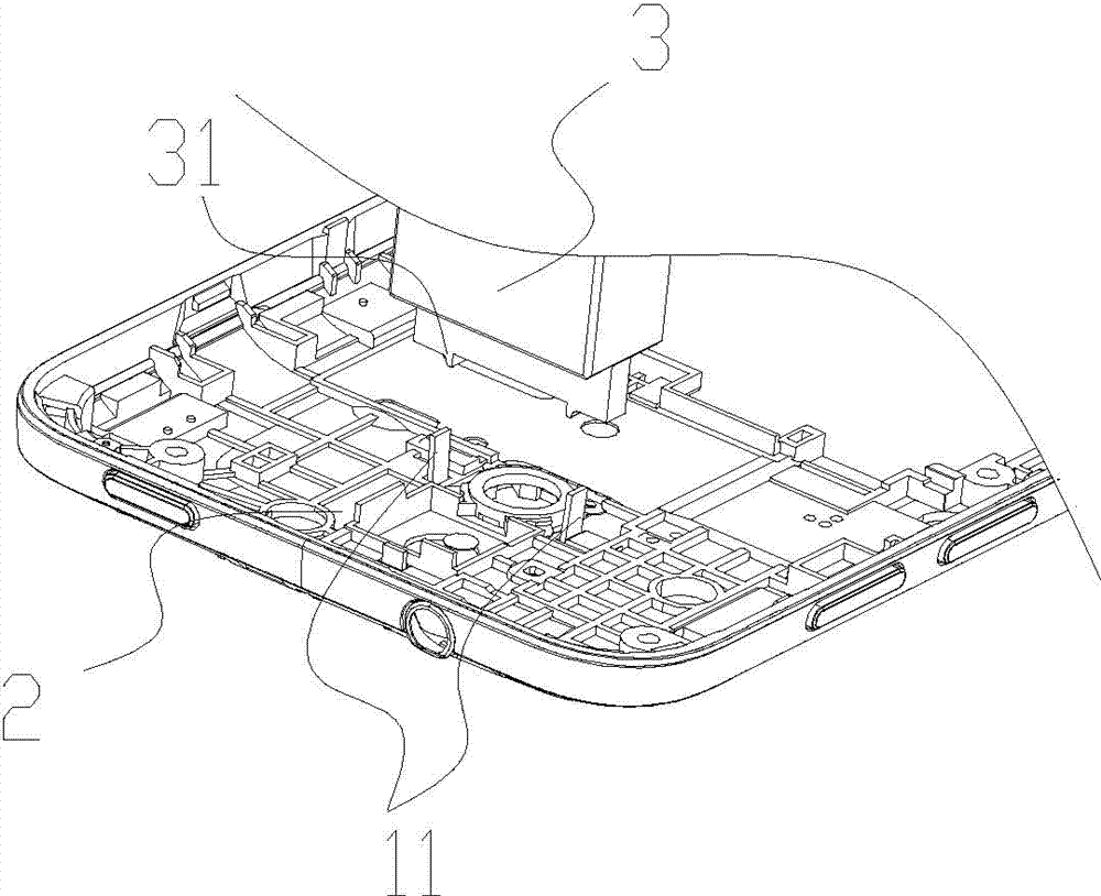
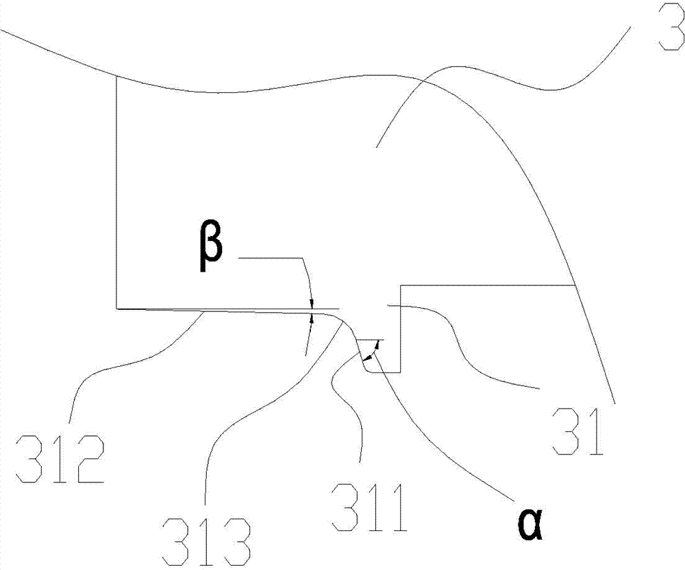
[0028] A specific implementation of a hardware pin bending mechanism of the present application, such as figure 2 , including fixing fixtures for fixing products with hardware 1 already installed, the figure 2 The pin 11 of the hardware 1 is clearly visible. The hardware 1 is located below the product and is covered in this figure. The above-mentioned technical features belong to the prior art. The innovation of this application is that the bending mechanism also includes a driving mechanism and The bending punch 3 drivingly connected with the driving mechanism, the punch end surface of the bending punch 3 is provided with two slope structures 31, and the slope structure 31 includes a half-bending slope 311 for side bending pin 11 and a A flattening slope 312 for flattening the pin 11 , an arc-shaped transition slope 313 is provided between the half-bending slope 311 and the fl...


PUM


Abstract

The invention relates to the technical field of hardware plug foot bending, in particular to a hardware plug foot bending mechanism and a bending method. The bending mechanism comprises a fixing jig, a driving mechanism and a bending plunger chip connected with the driving mechanism in a driving mode. The plunger chip end face of the bending plunger chip is provided with slope structures protruding outwards. Each slope structure comprises a half-bending slope for laterally bending plug feet and a pressing slope for pressing the plug feet, wherein the half-bending slope is connected with the pressing slope, and the slope structures correspond to the hardware plug feet in a one-to-one mode. According to the method, the bending plunger chip pushes and presses the hardware plug feet, the half-bending slopes abut against the hardware plug feet, the hardware plug feet are bent to be the angle of the half-bending slopes, and finally, the pressing slopes abut against the hardware plug feet until the hardware plug feet abut against the bending angle of the pressing slopes. The hardware plug foot bending mechanism and the bending method are low in cost and high in bending efficiency.

Description

technical field [0001] The present application relates to the technical field of hardware pin bending, in particular to a hardware pin bending mechanism and a bending method. Background technique [0002] Many products are assembled with hardware such as figure 1 As shown, the hardware 1 includes pins 11 for fastening to the product. In order to fasten the hardware 1 to the product, the pins 11 of the hardware 1 need to be bent to be horizontal or quasi-horizontal. First fix the product with the hardware 1 on the fixing fixture, and then bend the pin 11 of the hardware 1, and the bending process of the pin 11 is completed through two operating mechanisms and two processes. The first The first process is a half-bending process, which is that the half-bending mechanism applies force from the side of the pin 11 to bend the side of the pin 11 to 45°, and then the second process is a flattening process, which is a flattening mechanism for the pin 11. Apply downward pressure to ...

Claims


Application Information

Patent Timeline
Patent Type & Authority Applications(China)
IPC IPC(8): B21D39/00B21D37/10
Inventor 聂江黄江峰李坚夏江主
Owner DONGGUAN GOOD MARK NEW PRECISION TECH CO LTD
Why Eureka
Try Eureka