Spinning machine

A technology for spinning machines and spun yarns, which is applied to spinning machines, continuous winding spinning machines, textiles and papermaking, etc. It can solve problems such as longer time, long time for jointing operations, and difficulty in catching spun yarns. The effect of reducing time-consuming and improving productivity

Active Publication Date: 2014-01-01
MURATA MASCH LTD
View PDF10 Cites 7 Cited by
  • Summary
  • Abstract
  • Description
  • Claims
  • Application Information

AI Technical Summary

Problems solved by technology

[0006] Therefore, in the conventional spinning machine, when the first catching part fails to catch or guide the spun yarn, a series of operations during the piecing operation are performed from the beginning again, so the time spent on the piecing operation becomes longer.
In addition, in the conventional spinning machine, it cannot be judged as abnormal unless the operation of the piecing operation is repeated from the beginning, so the time until the alarm is activated becomes longer.
In addition, in the conventional spinning machine, when the winding device winds up the spun yarn guided to the piecing device by the second catching part, the spun yarn is traversed by the traversing device, so it is more difficult to catch the spun yarn by the second catching part. The case of spun yarn

Method used


Image

  • Spinning machine
  • Spinning machine
  • Spinning machine

Examples


Embodiment Construction

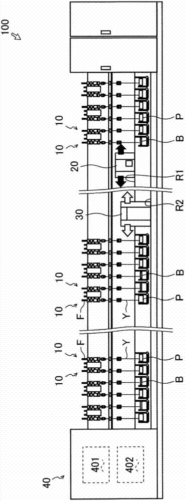
[0037] First, refer to figure 1 The spinning machine 100 will be briefly described. A blacked-out arrow shown in the figure indicates the traveling direction of the work vehicle 20 . In addition, blank arrows shown in the figure indicate the traveling direction of the doffing cart 30 .

[0038] The spinning machine 100 includes a plurality of spinning units 10 . The spinning machine 100 is provided with a work cart 20 , a doffing cart 30 , and a control device 40 .

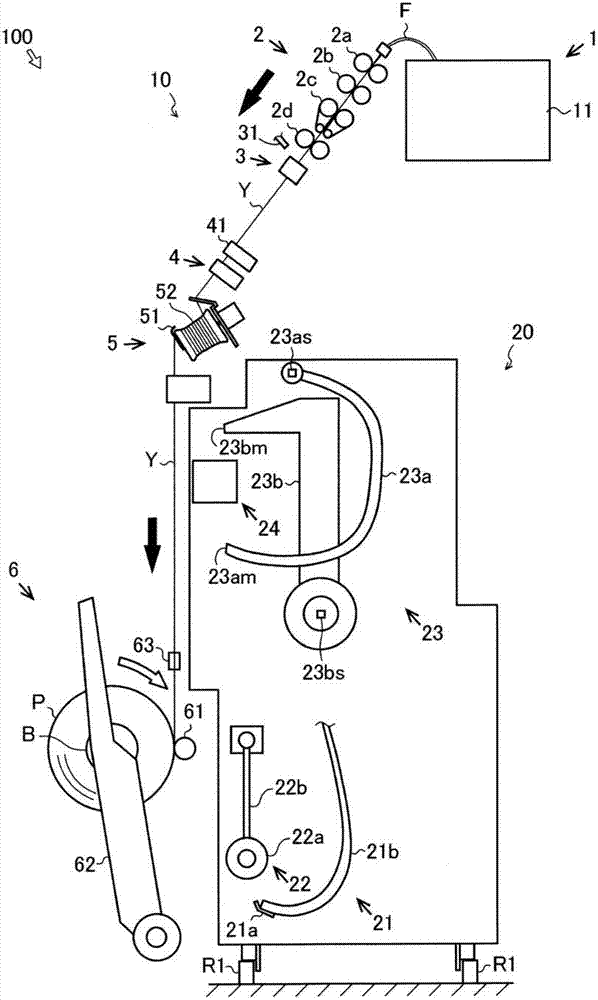
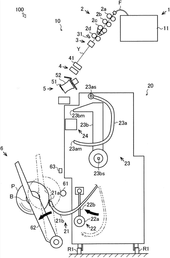
[0039] The spinning unit 10 is capable of drafting a fiber bundle F, and can manufacture a spun yarn Y by twisting the drafted fiber bundle F. The spinning unit 10 can manufacture a package P by winding the spun yarn Y. In addition, the detailed structure of the spinning unit 10 will be described later.

[0040]The work cart 20 can travel along a rail R1 extending in the direction in which the spinning units 10 are arranged. When the spun yarn Y becomes discontinuous in one spinning unit 10, the operation ca...


PUM


Abstract

A spinning machine comprises the components as follows: a spinning device (3), which twists a fibre bundle (F) to prepare a spun yarn (Y); a winding device (6), which winds the spun yarn (Y) to prepare a package (P); a first capture portion (23a), wherein when the spun yarn (Y) becomes discontinuous, the first capture portion captures the spun yarn at the side of the spinning device (3); and a control device (40), wherein when the first capture portion (23a) fails to capture the spun yarn (Y), the control device controls the first capture portion (23a) to enable the first capture portion (23a) to continue the capture action.

Description

technical field [0001] The present invention relates to the technology of spinning machines. Background technique [0002] Conventionally, a spinning machine including a plurality of spinning units is known (for example, refer to JP-A-2011-38225). Each spinning unit includes a spinning device for producing spun yarn and a winding device for producing a package. When the spun yarn becomes discontinuous in one spinning unit (the spun yarn is cut or broken), the spinning machine is provided with a work trolley that travels to the spinning unit to perform piecing work. The work cart includes a yarn joining device for joining the spun yarn and a guide device for guiding the yarn to the yarn joining device. [0003] The following briefly describes the spinning unit and the piecing work performed by the work cart. When the spun yarn becomes discontinuous in one spinning unit, first, the rotation of the package rotating in the winding direction is stopped, and the package is rota...

Claims


Application Information

Patent Timeline
Patent Type & Authority Applications(China)
IPC IPC(8): D01H15/013
CPCD01H15/00D01H1/115D01H15/002
Inventor 丰田贵大伊藤诚山田修司
Owner MURATA MASCH LTD
Why Eureka
Try Eureka