
Physical heart simulator

A cardiac and electrophysiological technology, applied in the simulation field of invasive electrophysiological surgery, can solve problems such as spending a lot of time

Inactive Publication Date: 2014-01-01
BIOSENSE WEBSTER (ISRAEL) LTD
View PDF8 Cites 20 Cited by
  • Summary
  • Abstract
  • Description
  • Claims
  • Application Information

AI Technical Summary

Problems solved by technology

Even when the learning curve is not steep, it often takes a significant amount of time to learn and perfect the procedure

Method used


Image

  • Physical heart simulator
  • Physical heart simulator
  • Physical heart simulator

Examples


specific Embodiment approach

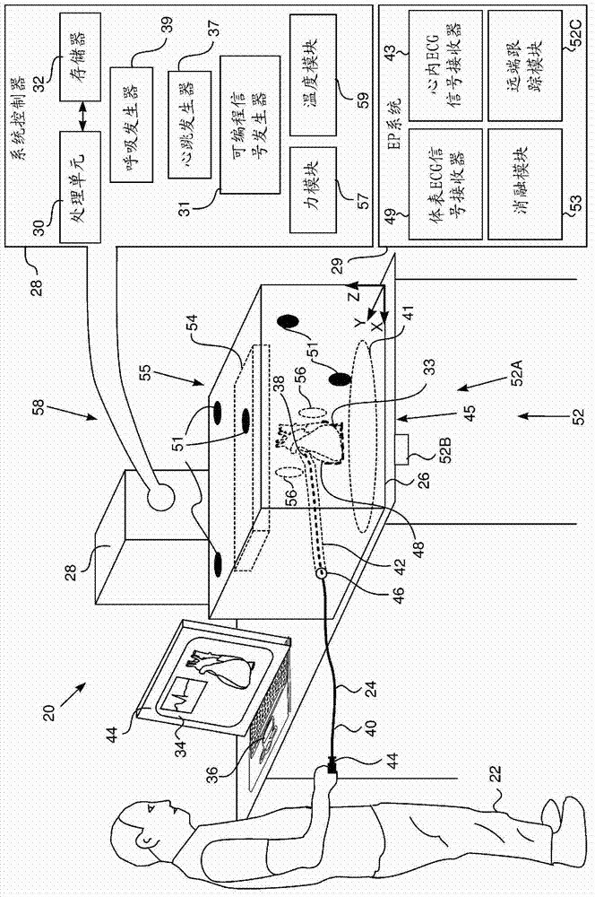
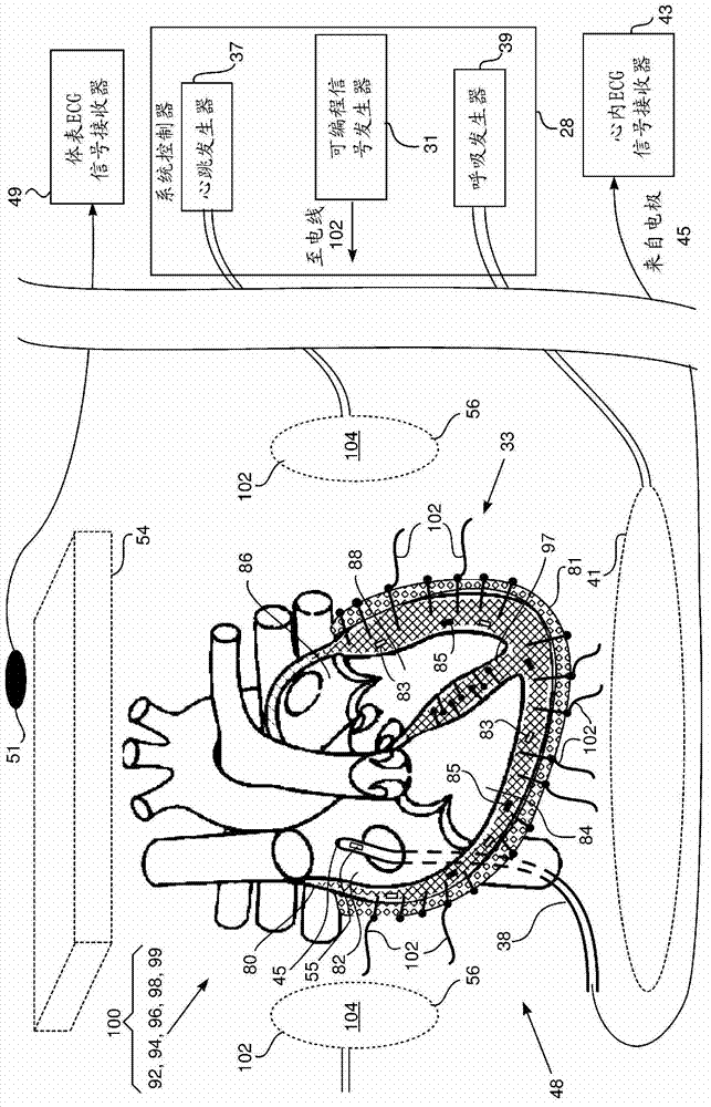
[0029] see now figure 1 , which is a schematic diagram showing a simulation system 20 according to an embodiment of the present invention. System 20 allows a system operator 22, typically a medical professional such as a physician, to perform a simulation of an invasive medical procedure. In a real medical procedure, an operator inserts a catheter stylet into a lumen of a patient, usually an organ such as the heart, and guides the distal end of the stylet by manipulating a controller located at the stylet's proximal end.

[0030] In the simulation system 20, an electrophysiological (EP) system probe 24 is inserted into a mock-up patient 26, which takes the place of a real patient in an actual procedure. The EP system probe 24 is substantially similar in construction and operation to probes used in real surgery, referred to herein as surgical probes. However, unlike surgical probes, EP system probes 24 are not required to meet the same stringent safety standards as surgical p...


PUM


Abstract

Apparatus, including a mockup cavity, simulating an actual body cavity of a human subject, wherein walls defining the mockup cavity comprise a tissue equivalent material (TEM). An array of electrodes are embedded in the walls. The apparatus further includes a programmable signal generator, connected to the electrodes, and configured to apply varying potentials to the array of electrodes so as to simulate electrophysiological potentials occurring in the actual body cavity on surfaces of the walls.

Description

technical field [0001] The present invention relates generally to invasive medical procedures, and in particular to the simulation of invasive electrophysiological procedures. Background technique [0002] There is generally a learning curve associated with any medical procedure, and depending on the procedure, this learning curve can be relatively "steep" in some cases. Even where the learning curve is not steep, it often takes a significant amount of time to learn and perfect the procedure. This time can be shortened if the surgery can be simulated. Contents of the invention [0003] An embodiment of the present invention provides a device, the device includes: [0004] a mock-up cavity simulating a real body cavity of a human subject, wherein the walls defining the mock-up cavity comprise tissue equivalent material (TEM); [0005] an array of electrodes embedded in the wall; and [0006] A programmable signal generator connected to the electrodes and configured to a...

Claims


Application Information

Patent Timeline
Patent Type & Authority Applications(China)
IPC IPC(8): G09B23/28A61B19/00
CPCG09B23/285G09B23/288G09B23/30
Inventor V.鲁宾斯泰恩M.巴-塔M.勒温
Owner BIOSENSE WEBSTER (ISRAEL) LTD
Learn More