Adjustable mirror rod with multiple degrees of freedom

An adjustable, degree-of-freedom technology, applied in optical observation devices, transportation and packaging, vehicle parts, etc., can solve the problems of inability to realize the axial movement of the vehicle rearview mirror, complex structure of the vehicle rearview mirror, and high manufacturing cost , to achieve the effect of increasing the range of space activities, simple structure and improving reliability

Inactive Publication Date: 2014-01-08
中外合资沃得重工(中国)有限公司
View PDF9 Cites 0 Cited by
  • Summary
  • Abstract
  • Description
  • Claims
  • Application Information

AI Technical Summary

Problems solved by technology

However, the structure of the vehicle rearview mirror is complicated, there are many parts, and the manufacturing cost is relatively high. The ball joint structure adopted in the utility model patent cannot realize the axial movement of the vehicle rearview mirror.

Method used


Image

  • Adjustable mirror rod with multiple degrees of freedom
  • Adjustable mirror rod with multiple degrees of freedom
  • Adjustable mirror rod with multiple degrees of freedom

Examples


Embodiment Construction

[0014] The present invention will be further described below in conjunction with drawings and embodiments.

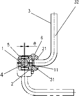
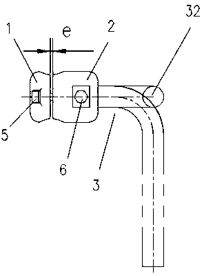
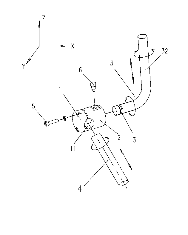
[0015] Such as Figure 1 ~ Figure 3 As shown, the present invention comprises a first clamping seat 1, a second clamping seat 2, a curved bar 3 and a straight bar 4, and the cylindrical first clamping seat 1 and the second clamping seat 2 are connected by two fastening screws 5 up and down. A clamping base 1 and a second clamping base 2 are fixedly connected into one body. One end of the curved rod 3 is hinged to the second clamping seat 2 , and one end of the curved rod 3 is rotatably inserted into the first circular hole 21 at one end of the second clamping seat 2 around its axis. One end of the bent rod 3 is provided with a ring groove 31 , and the bottom of the special screw 6 fixed on the second splint 2 is embedded in the ring groove 31 to prevent the bend rod 3 from falling out of the second clamp seat 2 .

[0016] A gap e of 2.5-3.5 mm is left between the dock...


PUM


Abstract

The invention discloses an adjustable mirror rod with multiple degrees of freedom. The adjustable mirror rod with multiple degrees of freedom comprises a first clamping base, a second clamping base, a bent rod body and a straight rod body. The first clamping base and the second clamping base are fixedly connected with each other through a plurality of fasteners. The bent rod body is hinged to the second clamping base. One end of the bent rod body can be inserted in a first circular hole in one end of the second clamping base in a rotating mode around the axis of the bent rod body. The straight rod body is hinged to the first clamping base and the second clamping base. One end of the straight rod body is inserted in a second circular hole in the butt joint position of the first clamping base and the second clamping base. The axis of the second circular hole is perpendicular to that of the first circular hole. A reflective mirror is fixed at one end of the bent rod body. The adjustable mirror rod with multiple degrees of freedom is simple in structure and convenient to use; the bent rod body and the straight rod body, perpendicular to each other, are hinged to the first clamping base and the second clamping base respectively, so that existing three degrees of freedom of activity in a space where the mirror rod is hinged to a mounting base ball are increased to five degrees of freedom in addition to three-axis rotation, wherein the other two degrees of freedom refer to the activity of bent rod end movement and straight rod end movement in the same space. Therefore, the spatial activity range of the mirror rod is greatly expanded, and the reliability of the reflective mirror in use is improved.

Description

technical field [0001] The invention relates to a visual mirror accessory of a vehicle or mechanical equipment, in particular to a multi-axis adjustable mirror rod, which belongs to the technical field of mechanical equipment accessories. Background technique [0002] When the operator drives a movable vehicle, construction machinery or operates mechanical equipment, he needs to use the rearview mirror to observe the road conditions on the left, right and behind him to ensure the safe driving of the vehicle or the safe operation of the mechanical equipment. The existing mirror rod structure has poor spatial mobility and cannot meet the user's requirements for the spatial position of the fixed object. The Chinese utility model patent of CN201042941 "a vehicle rearview mirror" proposes that the concave ball seat, the ball tile, the ball tile support plate, and the supporting ball tile on the mirror base are sequentially connected, and the cylindrical connecting piece passes th...

Claims


Application Information

Patent Timeline
Patent Type & Authority Applications(China)
IPC IPC(8): B60R1/02
Inventor 孙健顾赛男张莹
Owner 中外合资沃得重工(中国)有限公司
Why Eureka
Try Eureka