Hand-eye calibration method and system of robot, electronic device and storage medium
A hand-eye calibration and robot technology, which is applied to manipulators, program-controlled manipulators, manufacturing tools, etc., can solve the problems of complex calibration process and insufficient calibration accuracy, and achieve the effect of simple calibration process, reduced technology and easy operation.
- Summary
- Abstract
- Description
- Claims
- Application Information
AI Technical Summary
Problems solved by technology
Method used
Image

Examples
Embodiment 1
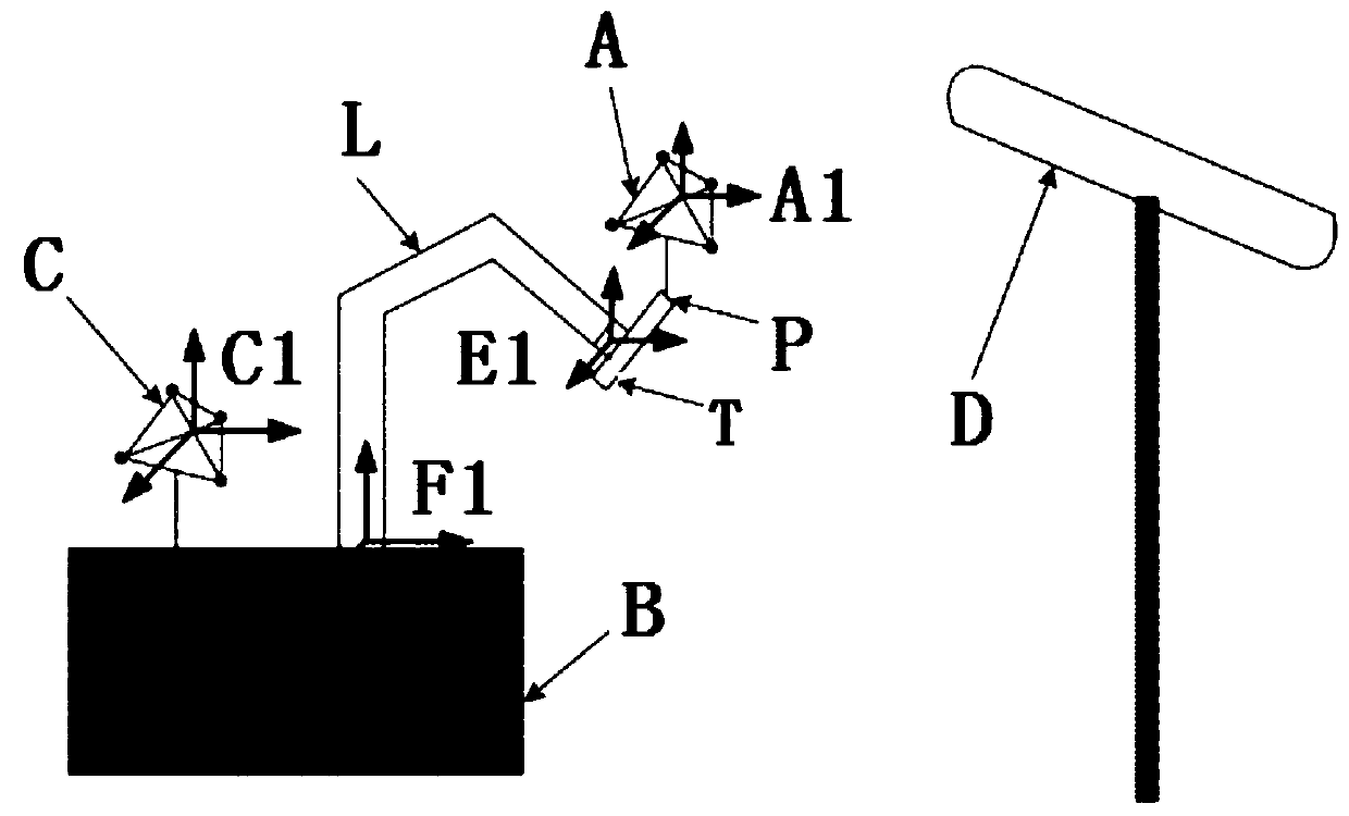
[0051] Such as figure 1 As shown, the end flange of the robot arm L is provided with an end tool T (such as a surgical instrument), the end tool T is provided with a first target ball A, and the base B of the robot is provided with a base The second target ball C with a relatively fixed seat, preferably, the second target ball C is fixed on the base B.
[0052] Among them, the position of the origin of the first target ball coordinate system A1 of the first target ball A and the second target ball coordinate system C1 of the second target ball C in the optical positioning coordinate system is read by the optical positioner D, and rotated through space The matrix change calculation obtains the spatial transformation relationship between the first target ball coordinate system A1 and the second target ball coordinate system C1. During the data collection process, the position and posture of the end point P of the end tool T in the first target ball coordinate system A1 and the sec...
Embodiment 2
[0082] Such as figure 1 As shown, the end flange of the robot arm L is provided with an end tool T (such as a surgical instrument), the end tool T is provided with a first target ball A, and the base B of the robot is provided with a base The second target ball C with a relatively fixed seat, preferably, the second target ball C is fixed on the base B.
[0083] Among them, the position of the origin of the first target ball coordinate system A1 of the first target ball A and the second target ball coordinate system C1 of the second target ball C in the optical positioning coordinate system is read by the optical positioner D, and rotated through space The matrix change calculation obtains the spatial transformation relationship between the first target ball coordinate system A1 and the second target ball coordinate system C1. During the data collection process, the position and posture of the end point P of the end tool T in the first target ball coordinate system A1 and the sec...
Embodiment 3
[0112] Figure 4 This is a schematic structural diagram of an electronic device provided in Embodiment 3 of the present invention. The electronic device includes a memory, a processor, and a computer program that is stored on the memory and can run on the processor. The processor implements the hand-eye calibration method of the robot in any one of Embodiments 1 or 2 when the processor executes the program. Figure 4 The displayed electronic device 30 is only an example, and should not bring any limitation to the function and application scope of the embodiment of the present invention.
[0113] Such as Figure 4 As shown, the electronic device 30 may be in the form of a general-purpose computing device, for example, it may be a server device. The components of the electronic device 30 may include, but are not limited to: the above-mentioned at least one processor 31, the above-mentioned at least one memory 32, and a bus 33 connecting different system components (including the ...
PUM
 Abstract
Description
Claims
Application Information
PatSnap Eureka turns technology decisions into work you can execute. Powered by our Innovation Knowledge Graph, it runs expert workflows across engineering, life sciences, materials and intellectual property. Get your review-ready output in minutes.


