Compression roller mechanism in rotary ironing machine

A technology of a drum ironing machine and a pressing roller mechanism, which is applied to ironing machines, washing devices, textiles and papermaking, etc., can solve problems such as poor flatness, save quantity, avoid displacement, and improve ironing quality.

Inactive Publication Date: 2014-01-08
TAIZHOU SUXING CLEANING PRINTING & DYEING MACHINERY MFG
View PDF3 Cites 0 Cited by
  • Summary
  • Abstract
  • Description
  • Claims
  • Application Information

AI Technical Summary

Problems solved by technology

Because of its low steam pressure and low operating cost, it is widely used by users. However, because the fabric is attached to the drum only by the binding force of the ironing belt, and there is a gap between the ironing belts, the ironing Poor flatness after leveling

Method used


Image

  • Compression roller mechanism in rotary ironing machine
  • Compression roller mechanism in rotary ironing machine

Examples


Embodiment 1

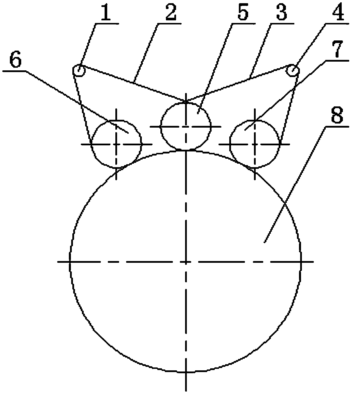
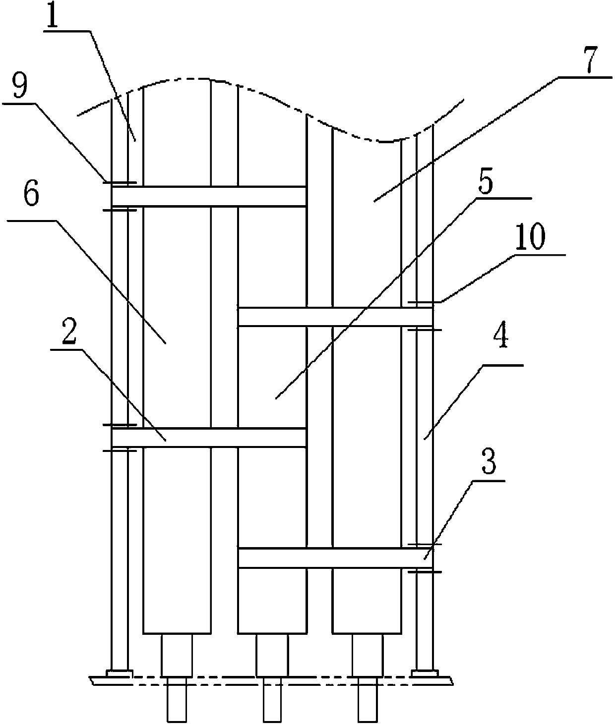
[0009] Embodiment one, in figure 1 with figure 2 Among them, the present invention provides a pressure roller mechanism in a drum ironing machine, which includes a pressure roller set and an ironing cylinder 8, the pressure roller set is attached to the ironing cylinder 8 by its own gravity, and the pressure roller set includes a left press Roller 6, middle pressure roller 5 and right pressure roller 7, middle pressure roller 5 is located on the longitudinal axis of ironing cylinder 8, left pressure roller 6 and right pressure roller 7 are respectively positioned at the left and right sides of middle pressure roller 5, on the left A left fixed pipe 1 is arranged above the roller 6, a right fixed pipe 4 is arranged on the upper part of the right pressure roller 7, and several left guide belts 2 are wound between the left pressure roller 6, the middle pressure roller 5 and the left fixed pipe 1. In this embodiment, two left guide belts 2 are wound between the left pressure rol...


PUM


Abstract

The invention discloses a compression roller mechanism in a rotary ironing machine. A compression roller set of the compression roller mechanism is attached to an ironing roller (8) by relying on the action of the self-gravity, a left compression roller (6) and a right compression roller (7) of the compression roller set are located on the left side and the right side of a middle compression roller (5) respectively, a left fixing tube (1) is arranged above the left compression roller (6), a right fixing tube (4) is arranged above the right compression roller (7), a plurality of left guide bands (2) wind among the left compression roller (6), the middle compression roller (5) and the left fixing tube (1), each left guide band (2) passes through the middle compression roller (5), the left compression roller (6) and the left fixing tube (1) in sequence and then forms a closed left guide band ring, a plurality of right guide bands (3) wind among the right compression roller (7), the middle compression roller (5) and the right fixing tube (4), and each right guide band (3) passes through the middle compression roller (5), the right compression roller (7) and the right fixing tube (4) in sequence and then forms a closed right guide band ring.

Description

technical field [0001] The invention relates to a roller ironing machine, in particular to a pressing roller mechanism used in the roller ironing machine. Background technique [0002] At present, the ironing machine in the industrial washing machinery in the known international standard mainly has two structural forms of drum type and groove type. Wrapped between the ironing belts on the outside of the drum, the moisture in the fabric to be ironed is heated and evaporated through contact heat transfer, and the ironing is achieved by the binding of the ironing belt. Because of its low steam pressure and low operating cost, it is widely used by users. However, because the fabric is attached to the drum only by the binding force of the ironing belt, and there is a gap between the ironing belts, the ironing The flatness after leveling is relatively poor. Contents of the invention [0003] The invention provides a pressure roller mechanism in a drum ironing machine, which ca...

Claims


Application Information

Patent Timeline
Patent Type & Authority Applications(China)
IPC IPC(8): D06F61/08
CPCD06F61/08
Inventor 袁祥
Owner TAIZHOU SUXING CLEANING PRINTING & DYEING MACHINERY MFG
Why Eureka
Try Eureka