Emergency stopping device

A technology for stopping equipment and equipment, applied in the direction of electrical components, electrical switches, circuits, etc., can solve the problem of increasing depth and size

Active Publication Date: 2014-01-08
SCHNEIDER ELECTRIC IND SAS
View PDF6 Cites 5 Cited by
  • Summary
  • Abstract
  • Description
  • Claims
  • Application Information

AI Technical Summary

Problems solved by technology

Therefore, it often has a particularly prominent form, which increases its depth dimension

Method used


Image

  • Emergency stopping device
  • Emergency stopping device
  • Emergency stopping device

Examples


Embodiment Construction

[0024] In a known manner, an emergency stop device is used for the control circuit and can be actuated by an operator to break the circuit in emergency situations.

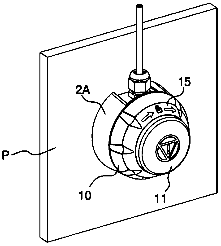
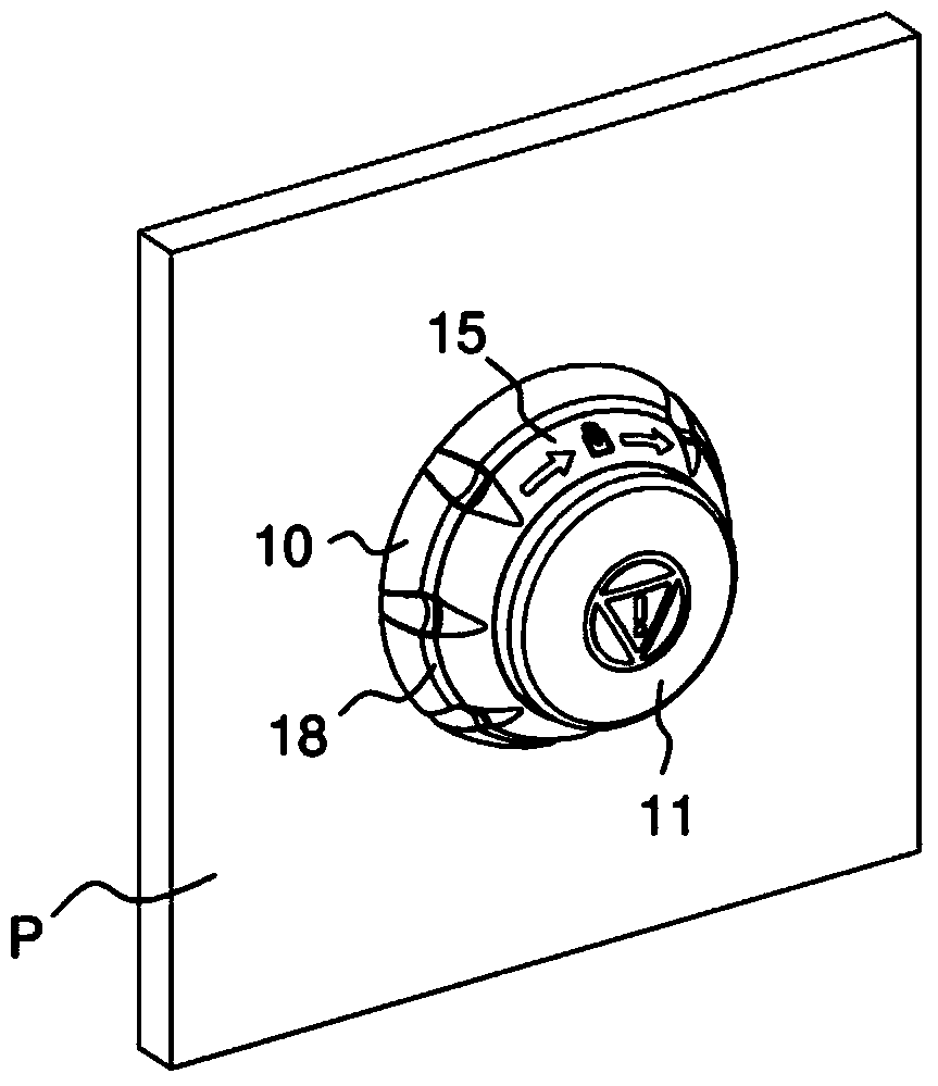
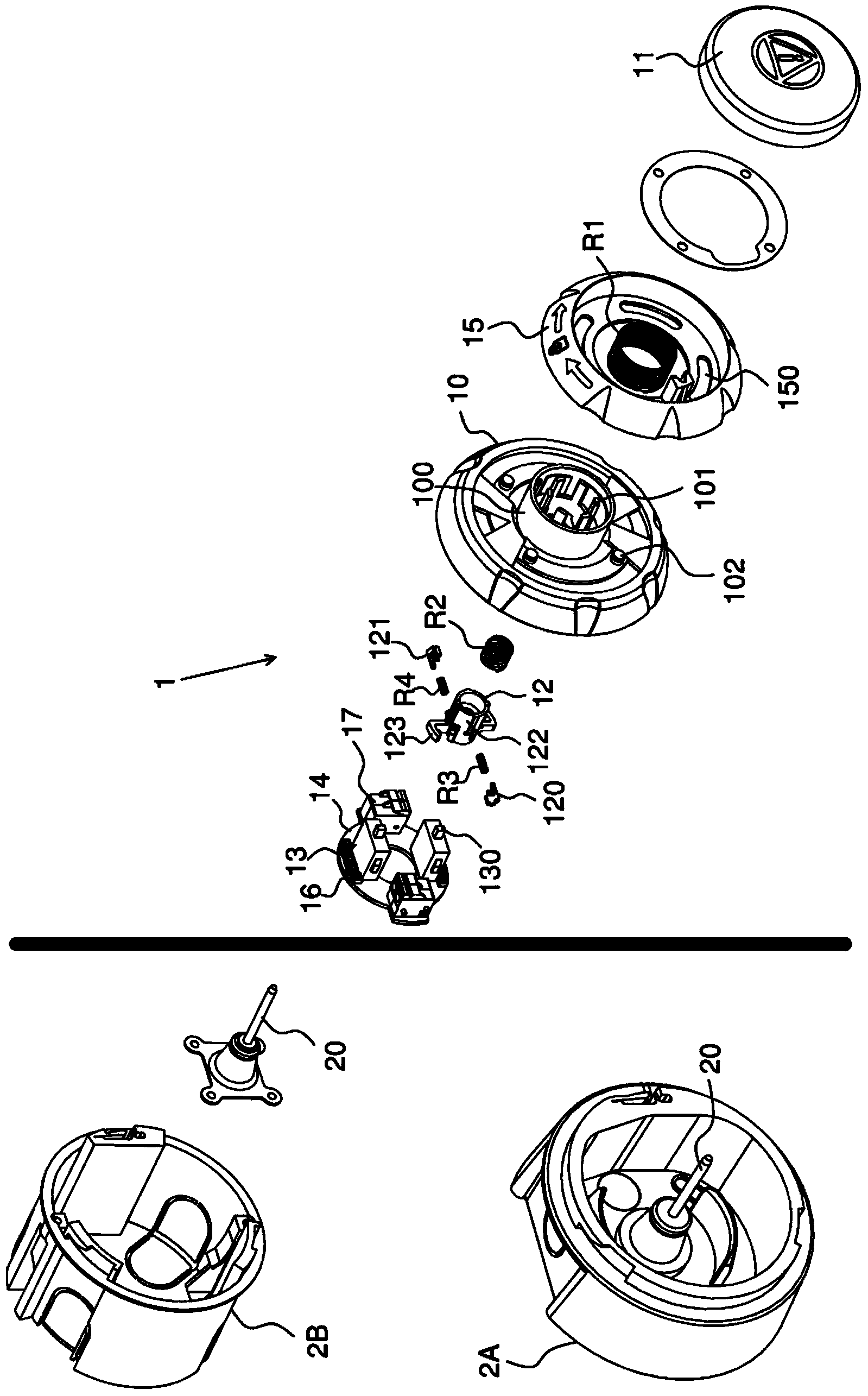
[0025] The emergency stop device of the present invention is installed according to which it protrudes from the wall P ( figure 1 ) or embedded in the wall ( figure 2 ) with two different structures. For both configurations, the emergency stop device consists of a housing 2A fitted on a housing 2A protruding from the wall P or a housing 2B embedded in the wall P ( figure 2 not visible in ) on the common structure. The common structure comprises a control assembly 1 intended to be fixed to a housing 2A, 2B and comprising a main body 10 .

[0026] For example, body 10 is circular and includes a central opening. The body also has a cylindrical collar 100 formed on the perimeter of the central opening, an inner cylindrical sleeve 101 and a disc 102 defined between the collar 100 and the sleeve 101 .

[0027] Th...


PUM


Abstract

The invention relates to an emergency stopping device, comprising a body (10), a control button (11) that is movable in translation along a control axis (X), at least one normally closed electrical contact unit (13), an actuation member (12) which can be actuated by said control button (11) so as to translate between a inoperative position and an actuated position, and which engages with the contact unit (13), a holding member (121) engaging with the actuation member (12) and capable of assuming a locking position for maintaining the actuation member in the actuated position thereof, and an unlocking ring (15) which is separate from the control button and which can be rotatably actuated, and which engages with the actuation member (12) so as to release the latter with a view to driving same toward the inoperative position thereof.

Description

technical field [0001] The invention relates to an emergency stop device of particularly compact construction. Background technique [0002] Today, known emergency stop devices, such as described in document US Pat. No. 7,790,996, comprise a control button movable in translation between two positions along a control axis and capable of actuating a pusher cooperating with an electrical contact unit. In order to unlock such an emergency stop device, the control button is actuated in a rotational manner. For ease of operation, the button must be shaped so that it is easy to grip relative to the rest of the device. Therefore, it usually has a particularly prominent form, which increases its depth dimension. [0003] Document EP2267743 describes an electric switch comprising: an actuator formed by a rotating ring movable between a rest position and an actuated position in which it remains locked; a cam for being rotationally driven by the rotating ring, a microswitch acting on...

Claims


Application Information

Patent Timeline
Patent Type & Authority Applications(China)
IPC IPC(8): H01H3/02
CPCH01H25/065H01H2003/0246H01H3/022
Inventor T.梅弗塔D.本尼
Owner SCHNEIDER ELECTRIC IND SAS
Why Eureka
Try Eureka