
Angle-adjustable channel steel bending machine

A technology for adjusting angles and bending machines, which is applied in the field of channel steel bending machines, can solve problems such as the inability to adjust the bending angle of channel steels, and achieve the effect of preventing damage

Inactive Publication Date: 2014-01-15
TIANJIN FANGHUA COMM ENG
View PDF8 Cites 2 Cited by
  • Summary
  • Abstract
  • Description
  • Claims
  • Application Information

AI Technical Summary

Problems solved by technology

Since the position between the existing two driven rollers and one driving roller is fixed, the bending angle of the channel steel cannot be adjusted

Method used


Image

  • Angle-adjustable channel steel bending machine
  • Angle-adjustable channel steel bending machine

Examples


Embodiment Construction

[0012] In order to enable those skilled in the art to better understand the technical solutions of the present invention, the present invention will be further described in detail below in conjunction with the accompanying drawings and preferred embodiments.

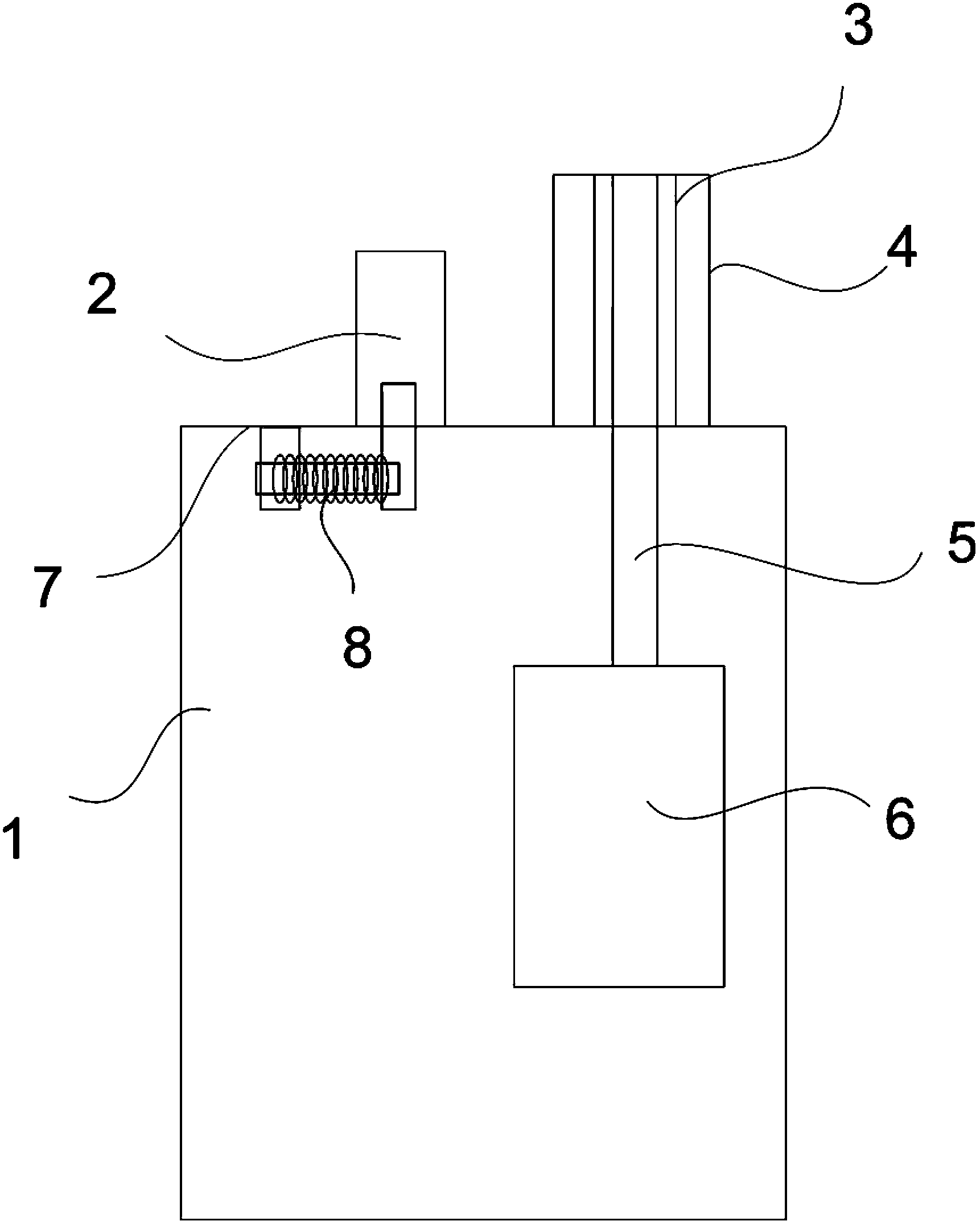
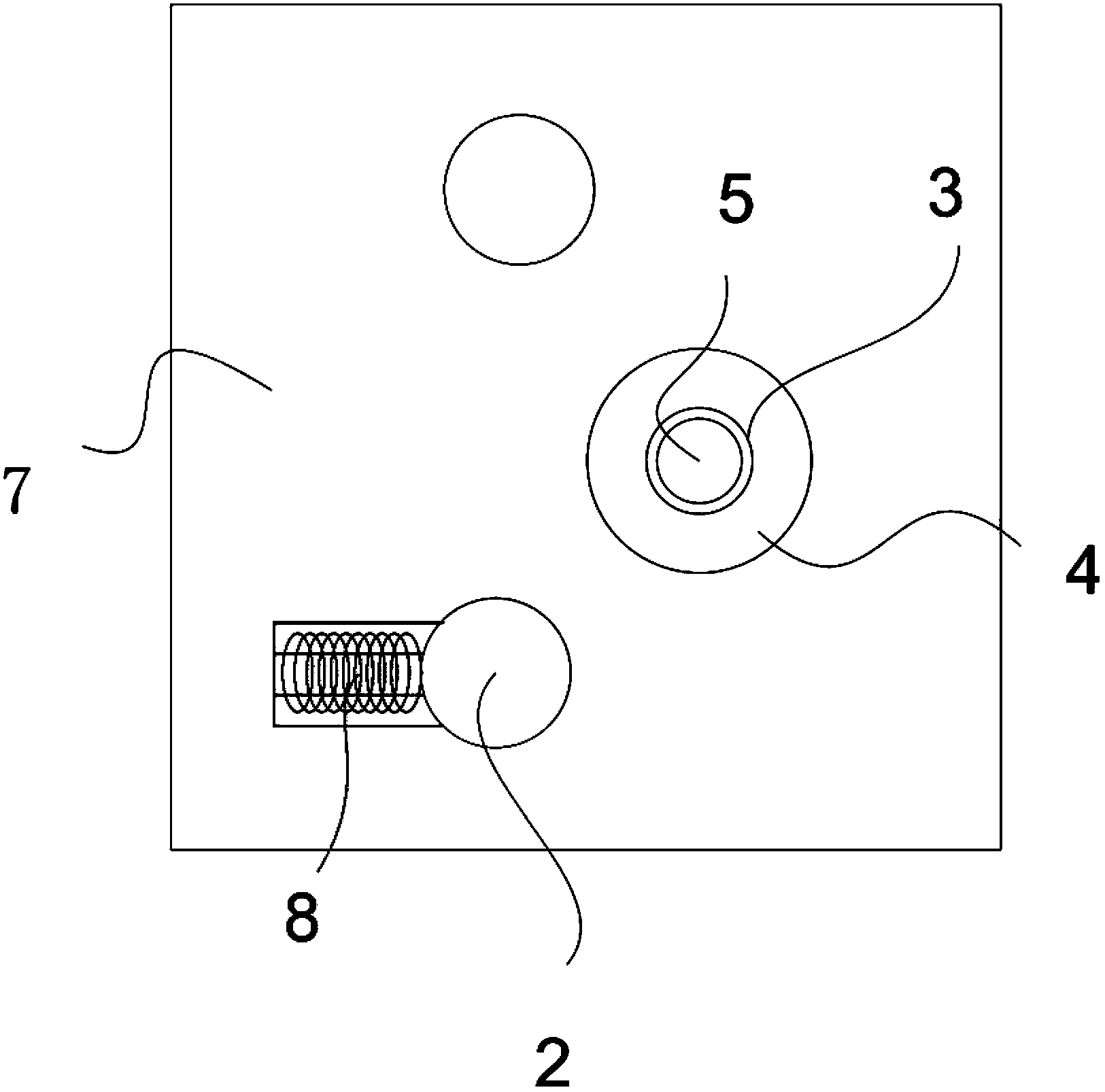
[0013] Such as figure 1 Shown, the present invention comprises work frame 1, is located at the workbench 7 of work frame upper end and is located at two driven rollers 2 and a driving roller 4 that axis center is parallel to each other on the end face of workbench, and described driving roller is arranged at two Between two driven rollers, the driving roller is driven by a motor-driven reducer 6, and a lead screw 8 for adjusting the position of the driven roller is provided under one of the driven rollers. The driving roller is connected with the driving roller shaft 5 by a spline 3 .

[0014] Since one of the two driven rollers is an adjustable driven roller that can move with the screw provided under the driven roller...


PUM


Abstract

The invention relates to a channel steel bending machine, in particular to an angle-adjustable channel steel bending machine. The angle-adjustable channel steel bending machine comprises a working frame, a working platform, two driven rolls and a driving roll, wherein the working platform is arranged at the upper end of the working frame, the driven rolls are arranged on the end surface of the working platform, and the axes of the driven rolls are parallel to each other. The driving roll is arranged between the two driven rolls and driven by a reduction box which is driven by a motor, and a lead screw used for adjusting the position of one of the driven rolls is arranged below the driven roll. Because one of the two driven rolls is an adjustable driven roll capable of moving along with the lead screw arranged below the driven roll, the bending angle is changed by adjusting the position of the driven roll, and therefore a shape needing machining can be realized. In addition, when the driving roll and a driving roll shaft are connected through a spline, the multipoint contact between the drive roll and the drive roll shaft can be better ensured, and damage to the driving roll due to too large stress is prevented.

Description

technical field [0001] The invention relates to a channel steel bending machine, in particular to an angle-adjustable channel steel bending machine. Background technique [0002] Channel steel bending machine is a device that bends channel steel according to a certain angle. It includes a work frame, a work table on the upper end of the work frame, two driven rollers and a driving roller whose axes are parallel to each other on the end surface of the work table. , the driving roller is arranged between two driven rollers, and the driving roller is driven by a reducer driven by a motor. During work, the channel steel is put between two driven rollers and a driving roller, and the driving roller rotates. The driven roller performs limit bending on the channel steel. Since the positions between the existing two driven rollers and one driving roller are fixed, the bending angle of the channel steel cannot be adjusted. Contents of the invention [0003] The technical problem ...

Claims


Application Information

Patent Timeline
IPC IPC(8): B21D7/08
Inventor 刘文华姜祥龙
Owner TIANJIN FANGHUA COMM ENG
Learn More