Rail clamping device

A technology of rail clamps and rail clamps, which is applied in the direction of traveling mechanism, load hanging components, transportation and packaging, etc., and can solve the problem of not being able to park for a long time

Inactive Publication Date: 2014-01-15
SHAANXI SHENGMAI PETROLEUM
View PDF0 Cites 3 Cited by
  • Summary
  • Abstract
  • Description
  • Claims
  • Application Information

AI Technical Summary

Problems solved by technology

In the actual production process, in order to meet the needs of the welding position, the tail box is often in a state of adjustment and movement, so it cannot be parked for a long time

Method used


Image

  • Rail clamping device
  • Rail clamping device

Examples


Embodiment 1

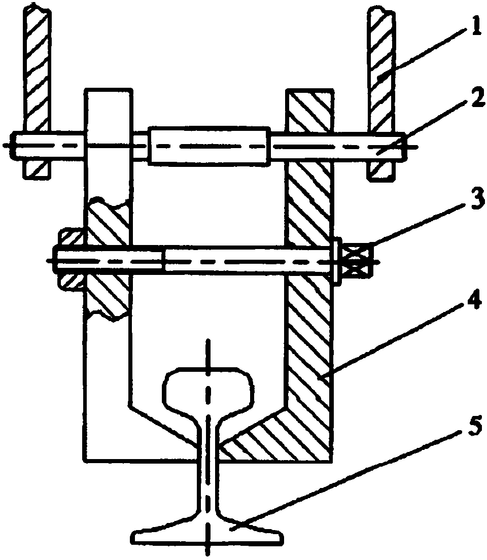
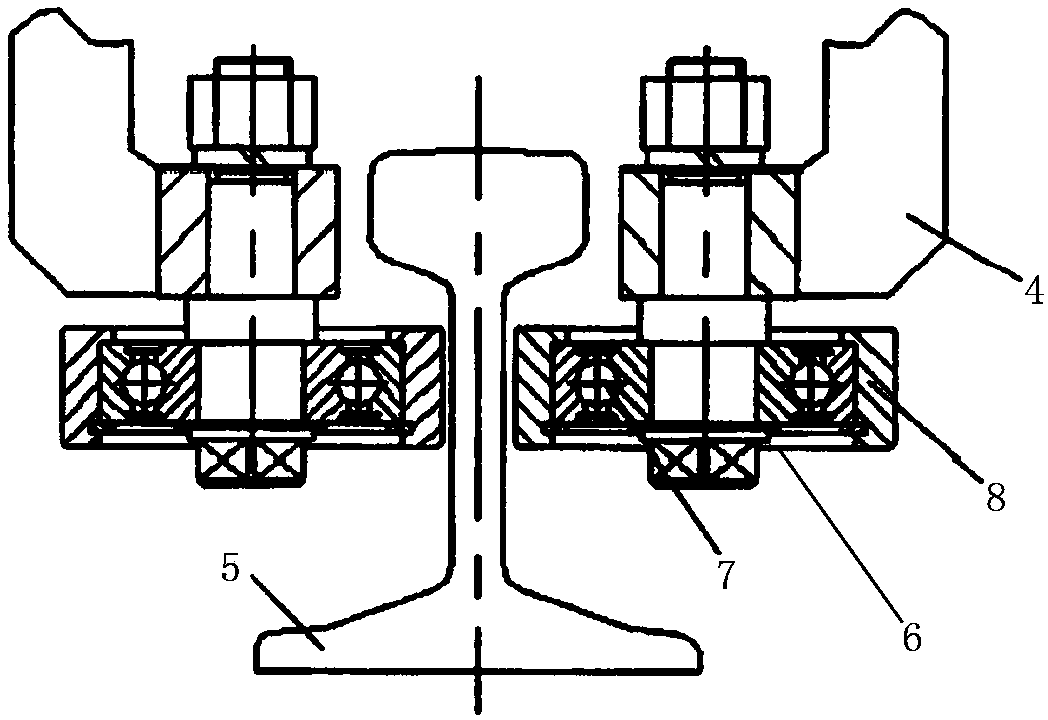
[0011] Such as figure 1 As shown, the rail clamp according to the present invention includes two rail clamps 4 and two rollers 6, the two rail clamps 4 are relatively in a hugging shape, and the two rail clamps 4 are connected by a connecting shaft , the roller shaft of the roller 6 is fixedly connected with the rail clamp 4, and the roller 6 is provided with a bearing 7 and an axle sleeve 8.

[0012] Rail gripper of the present invention will change sliding friction into rolling friction by the rail gripper 4 close to rail 5 part. And install bearing 7 and axle sleeve 8, make axle sleeve 8 and rail 5 rail surface both sides leave adjustment clearance during use. This enables the rail clamp to match the tail box is often in a state of adjustment and movement during the actual production process.


PUM


Abstract

The invention relates to a clamping device. A rail clamping device comprises two rail clamps and two rollers, wherein the two rail clamps embrace each other oppositely; the two rail clamps are connected through a connecting shaft; roll shafts of the rollers are fixedly connected with the rail clamps. The rail clamping device can not only move along with a walking device, but also play anti-sliding and guiding roles, and is safe, reliable, convenient and practical.

Description

technical field [0001] The invention relates to a clamping device. Background technique [0002] The excavator boom is welded from four steel plates with four main welds. In order to ensure the quality of the weld seam and the welding process, the welding positioner is often used in production to change the spatial position of the workpiece, so that one end of the boom is fixed, and the other end of the boom is rotated to adjust the welding position. When the workpiece is lifted and lowered asynchronously, the tail box moves horizontally accordingly. In order to ensure the safety and reliability of the tail box traveling device when it is working, and to avoid lateral tipping caused by instability, a relevant safety device-rail clamp must be installed on the walking frame. [0003] In the traditional rail clamp, the rail clamp is installed on the metal structure of the traveling chassis, and the jaws can be clamped on both sides of the rail surface or on the web of the rail...

Claims


Application Information

Patent Timeline
IPC IPC(8): B66C9/18
Inventor 王耀斌
Owner SHAANXI SHENGMAI PETROLEUM
Why Eureka
Try Eureka