Ultrasonic flowmeter support

A flowmeter and ultrasonic technology, applied in the field of brackets, can solve the problems of easy dust absorption, inconvenient reading, unclear reading, etc., and achieve the effect of convenient operation, easy installation and disassembly, and easy observation of detection data

Inactive Publication Date: 2020-03-20
西安西派测控技术有限公司
View PDF2 Cites 3 Cited by
  • Summary
  • Abstract
  • Description
  • Claims
  • Application Information

AI Technical Summary

Problems solved by technology

[0004] The purpose of the present invention is to provide an ultrasonic flowmeter bracket to solve the problems of inconvenient reading, unclear reading and easy adsorption of dust in the above background technology

Method used


Image

  • Ultrasonic flowmeter support
  • Ultrasonic flowmeter support
  • Ultrasonic flowmeter support

Examples


Embodiment 1

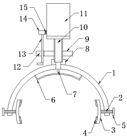
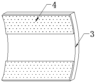
[0024] Such as figure 1 and image 3 As shown, it includes an arc-shaped fixing plate 1, the two sides of the arc-shaped fixing plate 1 are provided with locking mechanisms, the center of the bottom end of the arc-shaped fixing plate 1 is fixedly connected with an arc-shaped wire box 6, and the side wall of the arc-shaped wire box 6 A threading hole 7 is excavated in the middle of the ultrasonic flowmeter, which can collect the wires of the ultrasonic flowmeter, thereby protecting the wires and reducing the probability of corrosion and damage. It includes four screw rods 2 and four holding plates 5, the four screw rods 2 are threadedly connected with both sides of the arc-shaped fixed plate 1, the four holding plates 5 are respectively fixedly connected with one end of the four screw rods 2, and the four screw rods 2 The other end is fixedly connected with an arc-shaped splint 3, which can clamp pipes of different diameters and is convenient for clamping adjustment. The top a...

Embodiment 2

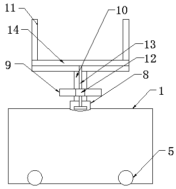
[0026] On the basis of Example 1, such as figure 2 As shown, the top of the connecting seat 8 is rotatably connected with a rotary tube 10, and the top of the rotary tube 10 is fixedly installed with a U-shaped clip 11, which can fix the meter head of the ultrasonic flowmeter and facilitate rotation at the same time. The middle part of the rotary tube 10 is fixed Connected with the grip ring 9, the grip ring 9 is convenient to hold and rotate, the side wall of the grip ring 9 is fixedly connected with the limit block 12, the inside of the limit block 12 is slidably connected with the transmission rod 13, and the top of the transmission rod 13 is fixedly connected with a fixed Bar 14, the side wall of the fixed bar 14 is fixedly connected with a brush bar 15, the brush bar 15 can wipe off the dust on the surface of the meter head, which is convenient for the operator to clearly observe the detection data, and the bottom end of the transmission rod 13 is fixedly connected with a...


PUM


Abstract

The invention discloses an ultrasonic flowmeter support. Arc-shaped fixing plate, locking mechanisms are arranged on the two sides of the arc-shaped fixing plate. The center of the bottom end of the arc-shaped fixing plate is fixedly connected with an arc-shaped wire box; a threading hole is formed in the middle of one side wall of the arc-shaped wire box; the middle of the top end of the arc-shaped fixing plate is fixedly connected with a connecting base. The locking mechanism comprises four screw rods and four holding plates; the four screws are in threaded connection with the two sides of the arc-shaped fixing plate correspondingly. The four holding plates are fixedly connected with one ends of the four screw rods respectively; the other ends of the four screw rods are fixedly connectedwith arc-shaped clamping plates; the top and the bottom of one side wall of each arc-shaped clamping plate are fixedly connected with anti-skid parts. According to the ultrasonic flow meter support,the locking mechanism is arranged, so that the ultrasonic flow meter support can flexibly meet the clamping requirements of pipelines with different diameters, the fixing steps are simple and more stable, Meanwhile, the ultrasonic flow meter support has certain skid resistance and is convenient to mount and dismount.

Description

technical field [0001] The invention relates to a bracket, in particular to an ultrasonic flowmeter bracket. Background technique [0002] Ultrasonic flow meter is based on the principle of "speed difference method" to measure the flow of liquid in a circular tube. It adopts advanced multi-pulse technology, signal digital processing technology and error correction technology to make the flow meter more adaptable to the environment of industrial sites. The measurement is more convenient, economical and accurate, and the products have reached the advanced level at home and abroad, and can be widely used in petroleum, chemical industry, metallurgy, electric power, water supply and drainage and other fields. [0003] In view of this, Chinese Patent No. CN207007246U proposes a kind of ultrasonic flow meter, when the signal component of the ultrasonic beam is sent from one side of the vibrating transceiver part to the other by vibrating the transceiver part, the vibration suppress...

Claims


Application Information

Patent Timeline
Patent Type & Authority Applications(China)
IPC IPC(8): G01F15/18G01F15/12G01F1/66
CPCG01F1/66G01F15/12G01F15/18G01F15/185
Inventor 李传鑫
Owner 西安西派测控技术有限公司
Why Eureka
Try Eureka