Wet joint construction method of T-shaped beam bridge floor system

A construction method and technology of wet joints, applied in the direction of bridges, bridge construction, bridge parts, etc., can solve the problems of low formwork reuse rate, difficulty in formwork removal, and easy damage to formwork support devices, so as to improve construction efficiency and repeat The effect of high utilization rate and convenience for next use

Active Publication Date: 2015-07-01
CHINA RAILWAY 19 BUREAU GRP CO LTD
View PDF6 Cites 3 Cited by
  • Summary
  • Abstract
  • Description
  • Claims
  • Application Information

AI Technical Summary

Problems solved by technology

[0003] The invention provides a construction method for the wet joints of the T-shaped beam bridge deck system, which solves the problem that the formwork support device is easily damaged and the formwork is removed in the construction process of the wet joints of the bridge deck in the existing double-line T-shaped beam erection. Difficulty and low template reuse issues

Method used


Image

  • Wet joint construction method of T-shaped beam bridge floor system
  • Wet joint construction method of T-shaped beam bridge floor system

Examples


Embodiment Construction

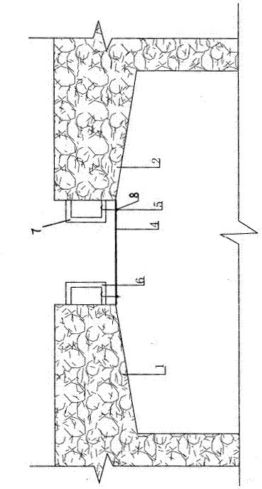
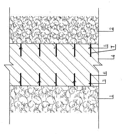
[0017] A T-shaped girder deck system wet joint formwork support device, comprising a left T-shaped beam 1 and a right T-shaped beam 2, a wet joint is arranged between the left T-shaped beam 1 and the right T-shaped beam 2, and the left T-shaped beam 2 is provided with a wet joint. The right end 6 of the embedded steel bar of the shaped beam 1 is set in the wet joint, the left end 7 of the embedded steel bar of the right T-shaped beam 2 is set in the wet joint, and two rows of reserved steel bars are arranged on the thin steel formwork 4 A thread is provided at the tail end of the hook 5, and the tail end of the hook 5 passes through the reserved hole and is screwed together with the nut 8, and the head of the hook 5 passing through the reserved hole 3 in the left row The upper hook is hooked on the right end 6 of the embedded steel bar of the left T-shaped beam 1, and the head hook of the suspension hook 5 passing through the reserved hole in the right row is hooked on the pre-...


PUM


Abstract

The invention discloses a wet joint construction method of a T-shaped beam bridge floor system. The wet joint construction method is used for solving the problems that a formwork erection device is easily damaged, formworks are removed with difficulty, and the reusing rate of the formworks is low in the formwork erection process for bridge floor wet joint in traditional erection of a double-line T-shaped beam bridge. The T-shaped beam bridge comprises a left T-shaped beam (1) and a right T-shaped beam (2), a thin steel formwork (4) is provided with two rows of preformed holes, threads are formed at the tail ends of lifting hooks (5), the tail end of each lifting hook (5) penetrates through the corresponding preformed hole and then is in thread connection with a nut (8), head hooks of the lifting hooks (5) penetrating through the left row of preformed holes (3) are hung on the right ends (6) of embedded bars of the left T-shaped beam, and head hooks of the lifting hooks (5) penetrating through the right row of preformed holes are hung on the left ends (7) of embedded bars of the right T-shaped beam. According to the formwork erection device in the wet joint construction method, a supporting frame is not arranged on the bridge floor, the damage caused by vehicle rolling is avoided, the reused rate of the template is high, and construction efficiency is improved.

Description

technical field [0001] The invention relates to a method for pouring the wet joints of the bridge deck in the erection of double-line T-shaped beams. Background technique [0002] When erecting a T-beam bridge, after the double-line T-beam erection is completed, three wet joints will be formed on the bridge deck. Under the standard line spacing, each wet joint is generally 30 cm wide and more than 30 meters wide. Long, the construction process requires the wet joints to be reinforced and cemented to complete the civil construction of the bridge deck. Before pouring the wet joints, the wet joints should be supported by formwork, and then the cement can be poured. The existing formwork support method is to use the hanging formwork and the structure of the center-to-center pull, that is, the formwork is made of wood formwork or bamboo. The rubber plate uses No. 12 fine-rolled rebar as the tie rod, and the tie rod is passed through the PVC pipe. A steel pipe or a piece of wood ...

Claims


Application Information

Patent Timeline
Patent Type & Authority Patents(China)
IPC IPC(8): E01D19/06
Inventor 薄春莲王传永
Owner CHINA RAILWAY 19 BUREAU GRP CO LTD
Why Eureka
Try Eureka