Insolation shielding device

A technology of shielding device and engaging part, applied in the direction of door/window protection device, window/door, building components, etc., can solve the problems of reduced positioning function, deterioration of thin-walled parts, ball jamming, etc., and achieve good positioning function. Effect

Active Publication Date: 2014-01-15
TACHIKAWA
View PDF5 Cites 4 Cited by
  • Summary
  • Abstract
  • Description
  • Claims
  • Application Information

AI Technical Summary

Problems solved by technology

As a result, the position where the protrusion and the end of the ball receiving portion contact the ball is different in the radial direction, and the ball is likely to be caught due to a slight gap difference.
[0011] In addition, in the structure disclosed in Patent Document

Method used


Image

  • Insolation shielding device
  • Insolation shielding device
  • Insolation shielding device

Examples


no. 1 approach

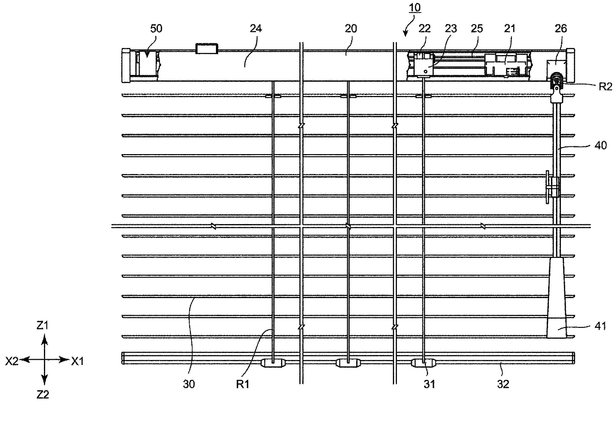
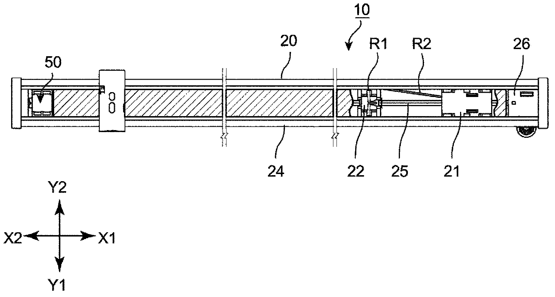
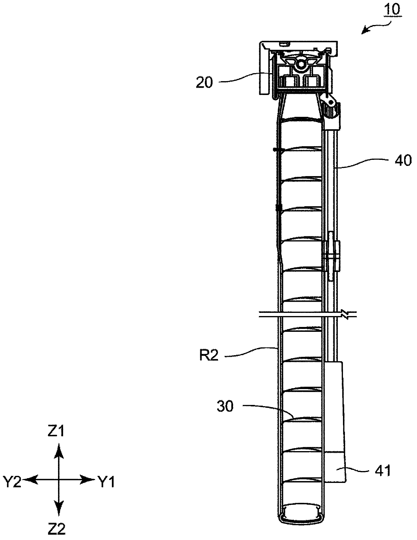
[0065] Hereinafter, the horizontal blind 10 as a sunlight shielding device according to the first embodiment of the present invention will be described with reference to the drawings. In addition, in the following description, the XYZ rectangular coordinate system may be used for description, and the longitudinal direction of the horizontal louver 10 is set as the X direction, and figure 1 Set the right end side of the X1 side, set the figure 1 The left end side of is set to the X2 side. Moreover, let the drooping direction (up-and-down direction) of a horizontal louver be Z direction, let an upper side be Z1 side, and let a lower side be Z2 side. In addition, the direction perpendicular to the X direction and the Z direction is referred to as the Y direction, the indoor side where the operation lever 40 is located is referred to as the Y1 side, and the opposite side is referred to as the Y2 side.

[0066]

[0067] Such as Figure 1 ~ Figure 3 As shown, in the horizontal ...

no. 2 approach

[0133] Hereinafter, the horizontal blind 10 which concerns on 2nd Embodiment of this invention is demonstrated based on drawing. In addition, the horizontal blind 10 in this embodiment has the same structure as the horizontal blind 10 in the above-mentioned first embodiment except for a click unit 50A. Therefore, in the following description, the impact unit 50A will be described and the description of other parts will be omitted. In addition, in this embodiment, the parts other than the impact unit 50A are described using the same symbols as those of the above-mentioned first embodiment.

[0134] Such as Figure 12 As shown, in the present embodiment, the structure of the impact roller 60A constituting the impact unit 50A is different from that of the impact roller 60 in the first embodiment described above. Such as Figure 13 As shown, in the present embodiment, two protrusions 61b are provided on the clutch ball sliding portion 61A of the impact roller 60A. Furthermore,...


PUM


Abstract

The invention provides an insolation shielding device which reliably constrains the rotation of a rotary shaft and achieves an excellent long-term positioning function. The insolation shielding device comprises: an inlaid body (60) which is rotatable in unison with a rotary shaft (25); a rotary body (70) which is mounted to rotate freely with respect to the rotary shaft (25) and is arranged adjacent to the inlaid body (60), and a casing (80), which has an interior space (S) in which the inlaid body (60) and the rotary body (70) are received. The inlaid body (60) is provided with a first engaging section (64) and the rotary body (70) is provided with a second engaging section (75) and a third engaging section (77). The casing (80) is provided with a fourth engaging section (83). Rotating the rotary shaft (25) causes the inlaid body (60) to rotate relative to the rotary body (70) so as to bring the first engaging section (64) and the second engaging section (75) into abutting engagement with each other. After the abutting engagement, the rotary body (70) is rotated in unison with the inlaid body (60), when the third engaging section (77) and the fourth engaging section (83) are brought into abutting engagement with each other, the rotation of the rotary body (70) in a direction of incurring interference with the fourth engaging section (83) is constrained.

Description

technical field [0001] The present invention relates to insolation shielding devices. Background technique [0002] A horizontal blind, which is a type of sun protection device, generally has a plurality of blades suspended from an upper beam via a direction control cord, and the horizontal blind is usually provided with a mechanism for adjusting the angle of the blades. As such a horizontal louver, there exist those disclosed by patent document 1 and patent document 2, for example. [0003] In the horizontal blind disclosed in Patent Document 1, the rotation of the rotating shaft to which the sleeve is attached is restricted by bringing a protrusion provided on the sleeve into contact with a ball. However, since the ball is accommodated in the ball storage portion and the ball can move in the ball storage portion, the rotation shaft can be rotated more than 360 degrees. [0004] In addition, in the horizontal blind disclosed in Patent Document 2, the extended portion of t...

Claims


Application Information

Patent Timeline
IPC IPC(8): E06B9/322
Inventor 冈村正
Owner TACHIKAWA
Why Eureka
Try Eureka