Locating grid

A technology for positioning grids and grids, which is applied in the direction of reducing greenhouse gases, nuclear power generation, and climate sustainability. The distribution is regular, avoiding a substantial increase and reducing the effect of heat transfer

Inactive Publication Date: 2014-08-06
CHINA NUCLEAR POWER TECH RES INST CO LTD +1
View PDF8 Cites 2 Cited by
  • Summary
  • Abstract
  • Description
  • Claims
  • Application Information

AI Technical Summary

Problems solved by technology

[0003] Among them, using the traditional positioning grid to locate the rod bundle components is a common positioning method for nuclear reactors at present. However, the traditional positioning grid is positioned by surface contact with the rod bundle components. Because of the surface contact method, it is impossible To avoid the impact on the heat transfer of the fluid; and because the flow and heat transfer process of the rod bundle elements is much more complicated under the supercritical condition than that under the subcritical pressure, the heat transfer deterioration generally occurs in the vicinity of the traditional spacer grid, and the obtained The heat transfer data are messy (such as figure 1 shown), and the temperature of the wall surface of the rod bundle element is too high, the result is not ideal
Moreover, the fixation of the fuel rods by the traditional positioning grid is relatively rigid and inflexible, and it is easy to get stuck with the fuel rods under high temperature and high pressure conditions
[0004] Furthermore, the wire-wrapping positioning method is currently the most widely used positioning method in fast reactors. The biggest advantage is that it has less impact on heat transfer, but the wire-wrapping positioning method has the disadvantages of weak fixation and instability

Method used


Image

  • Locating grid
  • Locating grid
  • Locating grid

Examples


Embodiment Construction

[0022] In order to describe the technical content and structural features of the present invention in detail, further description will be given below in conjunction with the implementation and accompanying drawings.

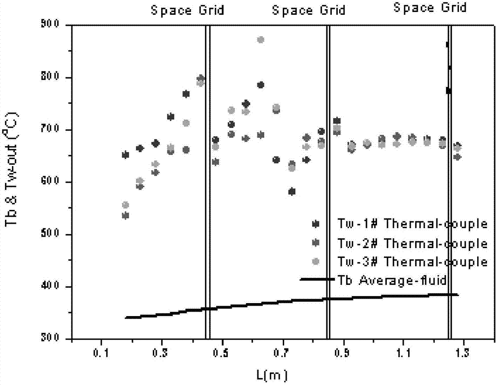
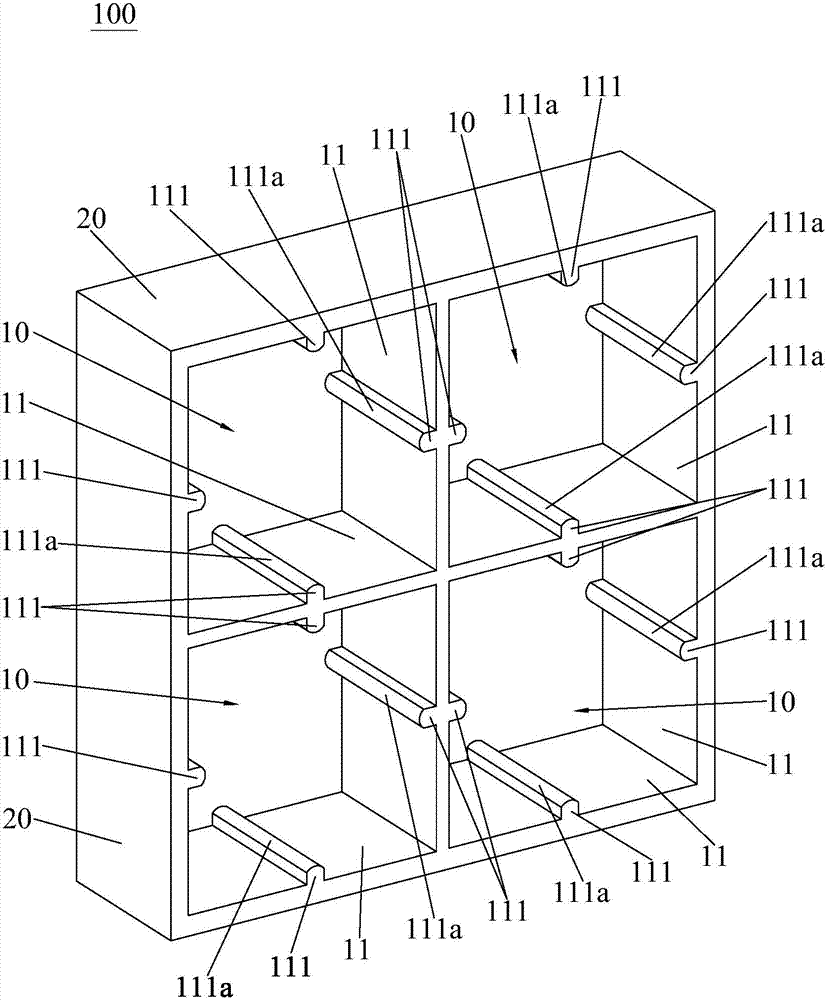
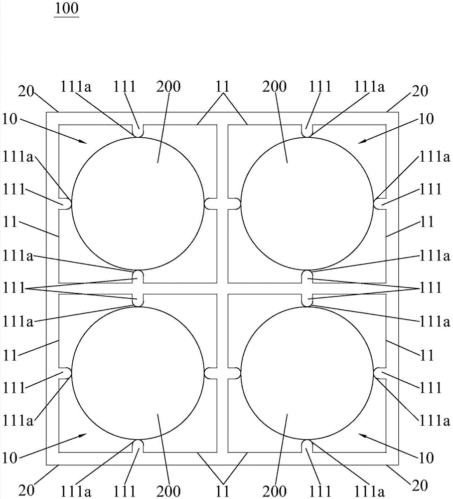
[0023] see figure 2 and image 3 , the positioning grid 100 of the present invention is suitable for positioning fuel rods 200 such as rod bundle components, wherein the positioning grid 100 of the present invention has a grid unit 10 with a hollow structure, and the fuel rods 200 are inserted into the grid unit 10 , the inner side wall 11 of the grid unit 10 is in point contact or line contact with the wall surface of the fuel rod 200 . Therefore, the spacer grid 100 of the present invention ensures a good positioning function for fixing the fuel rods 200, and enhances the fluid disturbance near the spacer grid 100; The structure of contact or line contact strengthens the fluid heat transfer in the area near the positioning grid 100, that is, the heat transfe...


PUM


Abstract

The invention provides a locating grid suitable for locating fuel rods. The locating grid comprises a grid unit with a hollow structure, wherein a fuel rod penetrates through the grid unit; an inner side wall of the grid unit is in point contact or line contact with a wall surface of the fuel rod. Therefore, the locating grid has a locating function of well fixing the fuel rod, and fluid disturbance near the locating grid is enhanced; according to the structure that the inner side wall of the grid unit is in point contact or line contact with the wall surface of the fuel rod, fluid heat transfer in an area near the locating grid is intensified, so that temperature distribution on the wall surface of the fuel rod is regular, and a phenomenon that the temperature on the wall surface of the fuel rod is greatly increased is avoided. Compared with a traditional locating grid, contact between the locating grid and the fuel rod is improved from surface contact to point contact or line contact, the influence on heat transfer of the wall surface of the fuel rod is greatly reduced, and the fuel rod is flexibly fixed. Moreover, compared with a wire winding locating mode with low heat transfer influence, the fixing effect is better.

Description

technical field [0001] The invention relates to the technical field of nuclear reactor thermal hydraulic rod bundle experiments, in particular to a positioning grid suitable for positioning fuel rods. Background technique [0002] In the experimental research on the bundle of nuclear reactors, it is necessary to locate the fuel rods such as the bundle components, and the existing common methods for positioning the bundle components are: using the traditional positioning grid to locate the rod bundle components and positioning by winding wires. [0003] Among them, using the traditional positioning grid to locate the rod bundle components is a common positioning method for nuclear reactors at present. However, the traditional positioning grid is positioned by surface contact with the rod bundle components. Because of the surface contact method, it is impossible To avoid the impact on the heat transfer of the fluid; and because the flow and heat transfer process of the rod bun...

Claims


Application Information

Patent Timeline
Patent Type & Authority Applications(China)
IPC IPC(8): G21C3/34
CPCY02E30/40Y02E30/30
Inventor 李虹波卢冬华周桐杨珏
Owner CHINA NUCLEAR POWER TECH RES INST CO LTD
Why Eureka
Try Eureka