A self-exciting back-rotating jet supercharger

A supercharger and self-excitation technology, which is applied in jet pumps, non-displacement pumps, machines/engines, etc., can solve the problems of low momentum exchange efficiency, low injection supercharging efficiency, long injector length, etc., and achieve shortening The effect of injector size, enhanced anti-fluctuation ability, and reduced energy dissipation

Active Publication Date: 2018-12-21
DALIAN UNIV OF TECH
View PDF1 Cites 0 Cited by
  • Summary
  • Abstract
  • Description
  • Claims
  • Application Information

AI Technical Summary

Problems solved by technology

[0003] However, the mixing chamber of the traditional injector supercharger mainly performs axial momentum exchange, the momentum exchange efficiency is low, the mixing boundary layer is thin and long, the injection boosting efficiency is low, the adjustment range is small, the operating elasticity is low, and the injector length is long. Applications are limited in many fields
The currently existing dynamic strong swirl ejector (CN201510286589.0) uses external excitation to achieve strong swirl ejection, and has a complex structure and sealing requirements

Method used


Image

  • A self-exciting back-rotating jet supercharger
  • A self-exciting back-rotating jet supercharger
  • A self-exciting back-rotating jet supercharger

Examples


Embodiment 1

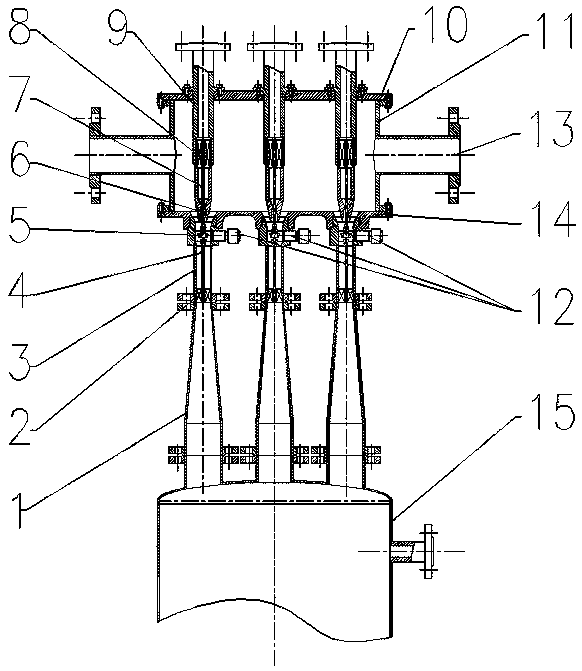
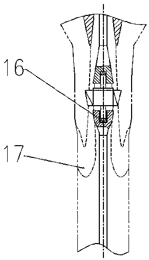
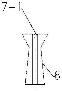
[0026] Figure 1 shows the overall structure of a self-energized back-swivel booster injector. The high-pressure main jet of the self-exciting back-rotating booster injector enters from the driving nozzle seat 9, and after being rectified by the front rectifying support ring 8, the driving nozzle 6 speeds up and reduces pressure, forming a low-pressure area at the front end of the mixing area, driving the suction chamber cylinder 11 The internal fluid is sucked into the supercharger mixing chamber 3 for mixing, usually the injector mixing boundary layer sees figure 2 The common mixed boundary layer schematic area 17 is shown, in which the self-excited swirl rotor 5 is set, and the fluid flow drives the self-excited swirl rotor 5 to rotate, generating disturbance, thickening the mixed boundary layer, and enhancing momentum exchange. The mixed fluid then flows through the supercharger diffuser chamber 1 and supports the rectification ring 2 for energy recovery and pressure recov...

Embodiment 2

[0029] Image 6 It shows the actual assembly of 7 sets of self-excited back-rotating booster injectors in parallel. Multiple sets of injectors are arranged in parallel in a circular ring, independent of each other and independent of each other. The number of openings can be selected by oneself. The suction chamber is shared by multiple sets of equipment, and two suction chamber suction ports 13 are welded symmetrically on the left and right sides of the suction chamber cylinder body 11, which are low-pressure fluid suction ports. The upper end cover 10 of the suction chamber and the lower end cover 14 of the suction chamber are connected with the flange bolts of the cylinder body 11 of the suction chamber, and the gaskets are sealed to form an integrally sealed low-pressure fluid suction chamber. The self-excited back-spin booster injector drive nozzle seat 9 is bolted to the upper end cover 10 of the suction chamber, and the supercharger mixing chamber 3 is threaded to the lo...


PUM


Abstract

The invention discloses a self-excitation back rotating type jetting supercharger and belongs to the field of fluid jetting supercharging. The jetting supercharger comprises an inner rectifying assembly and a zooming work cavity. According to the core, a self-excitation back rotating flow rotor at the front end of a supercharger mixing chamber is used for inducing the three-dimensional momentum gradient, a mixed boundary layer is thickened, one-way momentum exchange is changed into multi-dimensional momentum exchange, the fluid mixing efficiency is improved, and a back rectifying supporting ring is matched for recycling tangential energy. Multiple sets of supercharging jetting devices are adopted and are connected in parallel for set design, and a system adjusting function is strengthened. According to the supercharger, disturbance of the self-excitation rotor is utilized, the mixed boundary layer is thickened, and the length of a mixed section can be effectively reduced; the open area of drive nozzles is adjustable, and operation elasticity of the device can be effectively strengthened due to the fact that the multiple sets of nozzles are used simultaneously. The whole device is simple in structure, convenient to maintain and capable of being widely suitable for single-phase or multi-phase fluid supercharging.

Description

technical field [0001] The invention relates to a self-excited back-rotating jet supercharger, which belongs to the technical field of fluid jet supercharging. Background technique [0002] The ejector uses the jet action of the high-pressure fluid to pump the low-pressure fluid for mass transfer and momentum exchange, thereby completing the pressurization effect of the low-pressure gas. The ejector has the advantages of simple structure, convenient disassembly and assembly, safety and reliability, and long practical life. It can be widely used in fluid pressurization and vacuum extraction, and is not sensitive to complex working conditions such as flammable and explosive gases and impurities. At present, ejectors are widely used in refrigeration, metallurgy, aviation, natural gas collection, seawater desalination, sewage treatment and other technical fields. [0003] However, the mixing chamber of the traditional injector supercharger mainly performs axial momentum exchang...

Claims


Application Information

Patent Timeline
Patent Type & Authority Patents(China)
IPC IPC(8): F04F5/00F04F5/46F04F5/48
CPCF04F5/00F04F5/461F04F5/48
Inventor 代玉强姚轶智陶盛洋刘航赵顶胡大鹏武锦涛张大为
Owner DALIAN UNIV OF TECH
Why Eureka
Try Eureka