

High-temperature heat pipe with inner insertion spring and spiral fin
A high-temperature heat pipe and helical fin technology is applied in the engineering application field of heat transfer, which can solve the problems of poor limit condensation effect and low heat transfer coefficient at cold start, improve economy and operation reliability, and increase heat transfer. Area, good condensation effect
- Summary
- Abstract
- Description
- Claims
- Application Information
AI Technical Summary
Problems solved by technology
Method used
Image

Examples
specific Embodiment approach 1
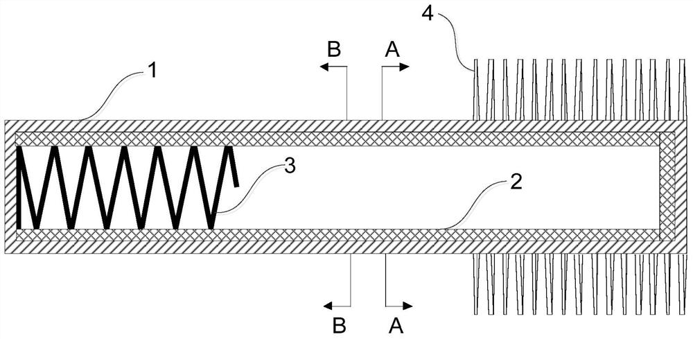
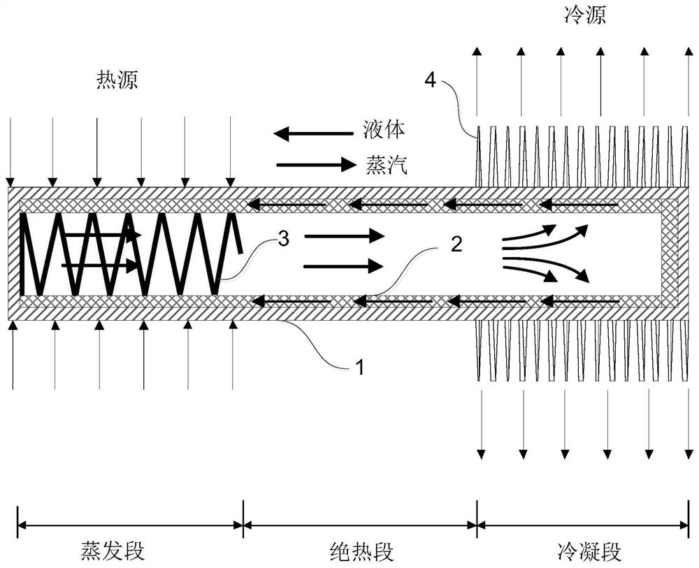
[0021] Specific implementation mode one: combine Figure 1 to Figure 4 Describe this embodiment, a high-temperature heat pipe with an internal spring and external spiral fins described in this embodiment, the high-temperature heat pipe includes a tube shell 1;
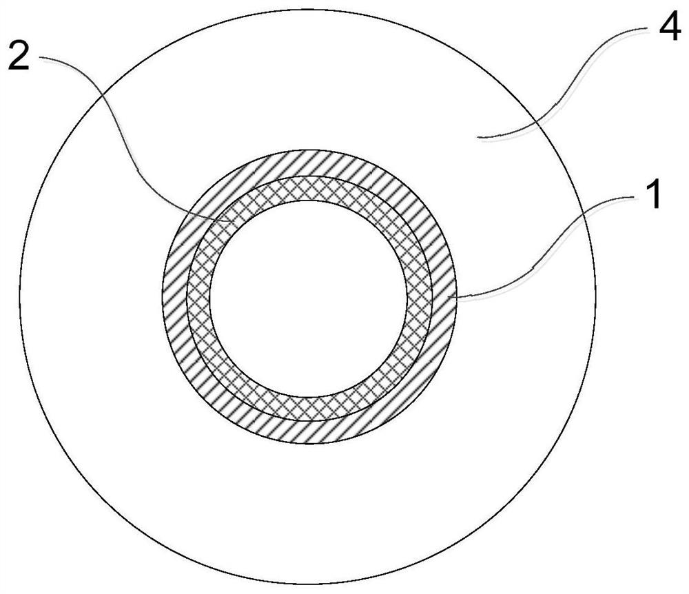
[0022] The shell 1 is a cylindrical structure with both ends closed;
[0023] The high-temperature heat pipe also includes a capillary core 2, an insert spring 3 and fins 4;
[0024] One end of the tube shell 1 is an evaporation section, the other end of the tube shell 1 is a condensation section, and an adiabatic section is between the evaporation section and the condensation section of the tube shell 1; wherein, the heat source acts on the evaporation section of the tube shell 1, and the tube The condensation section of shell 1 dissipates heat from the cold source;
[0025] The capillary core 2 is arranged on the inner side wall of the tube shell 1;
[0026] The insert spring 3 is a helical structure, and is arran...
specific Embodiment approach 2
[0029] Embodiment 2: This embodiment further limits the high-temperature heat pipe with an internal spring and spiral fins described in Embodiment 1. In this embodiment, the internal spring 3 is made of high-temperature ceramics.
[0030] In this embodiment, the insert spring 3 is made of high-temperature ceramics. The high-temperature ceramic material has a high melting point and has the characteristics of high-temperature resistance, which can adapt to the high temperature of the evaporation section of the shell 1. Moreover, the high-temperature ceramic material has good stability and is not easy to mix with the working fluid. The occurrence of chemical reactions or physical changes ensures that the high-temperature heat pipe has a stable heat transfer performance, so that the high-temperature heat pipe described in this embodiment has a long working life and the possibility of industrial application.
specific Embodiment approach 3
[0031] Embodiment 3: This embodiment is to further limit the high-temperature heat pipe described in Embodiment 1, which is a high-temperature heat pipe with internal springs and spiral fins. In this embodiment, the fins 4 are in a spiral structure.
[0032] In this embodiment, the spiral structure of the fins 4 can enhance the convective heat dissipation process of the condensation section of the shell 1 and reduce the flow resistance of the fluid during the heat dissipation process.
PUM
 Abstract
Description
Claims
Application Information