
Installing structure of independent suspension system

A technology of installation structure and independent suspension, applied in suspension, elastic suspension, transportation and packaging, etc., can solve the problems of poor stress state of installation structure, affecting work efficiency, large impact force, etc., and achieve good guiding and positioning functions , Low strength and precision requirements, and the effect of improving strength and reliability

Inactive Publication Date: 2017-03-22
XUZHOU HEAVY MASCH CO LTD
View PDF6 Cites 2 Cited by
  • Summary
  • Abstract
  • Description
  • Claims
  • Application Information

AI Technical Summary

Problems solved by technology

[0008] 1. When the vehicle is running, the vertical, longitudinal and lateral loads transmitted by the wheels cannot be effectively separated, and will be superimposed into a large impact force on the oil cylinder and frame structure. Therefore, the stress state of the installation structure is relatively Poor and easily damaged
[0009] 2. The brackets on both sides of the frame box, due to welding deformation and welding errors, etc., when assembling the independent suspension system, in order to ensure the assembly accuracy, the brackets need to be welded and repaired on site, which affects work efficiency
[0010] 3. Vehicles matching this type of structure are subject to greater impact when driving. Therefore, the selection of vehicles with this type of structure requires that the parts in the independent suspension system have higher strength and impact resistance, which increases the cost of the vehicle.
[0011] To sum up, the current installation of the independent suspension system of wheeled cranes is a rigid connection, the system is subject to large impact, the structure is easily damaged, and the requirements for parts are high, which seriously hinders the application and promotion of the independent suspension system.

Method used


Image

  • Installing structure of independent suspension system
  • Installing structure of independent suspension system
  • Installing structure of independent suspension system

Examples


Embodiment Construction

[0028] The present invention will be described in detail below with reference to the accompanying drawings and specific embodiments.

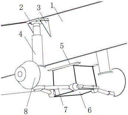
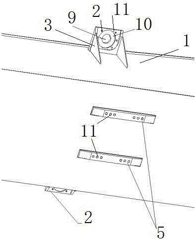
[0029] An installation structure of an independent suspension system, a thick plate 5 is welded on the lower bottom surface of the frame 1 in a butt manner, and the thick plate 5 and the lower bottom surface of the frame 1 have a certain height difference. The hole 11 is used to fix the base 6 .

[0030] The protruding surface of the thick plate 5 can be finished after the overall welding of the frame 1 is completed, which not only facilitates the structural tailoring of the frame 1, but also improves the flatness of the mounting surface of the thick plate 5 and the thickness of the thick plate 5 and the frame. 1 The accuracy of the height difference of the base plate.

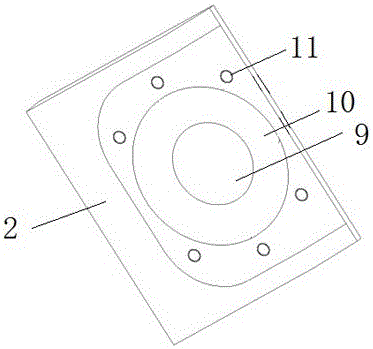
[0031] Two sides of the frame 1 are welded with a support 2 and a reinforcing plate 3 , and a stepped plane and a mounting screw hole 11 are processed on the support 2 .

[0...


PUM


Abstract

The invention discloses an installing structure of an independent suspension system. The installing structure of an independent suspension system is characterized by comprising a plurality of supports, bases and pulling rods. The bases are arranged at the bottom of a vehicle frame; the pulling rods are arranged on the outer side of the bases; the lower end of an oil cylinder is fixed; the supports are horizontally and vertically arranged on the external side surfaces of two sides of the vehicle frame; and the top end of an oil cylinder is fixed. The installing structure of the independent suspension system provided by the invention consists of the supports arranged on the external side surfaces of two sides of the vehicle frame and the bases arranged at the lower portion of the vehicle frame; the top and bottom of the installing structure are positioned and installed, respectively; and thus a flexible dynamic balance mechanism can be formed. When a vehicle runs, longitudinal, horizontal and vertical loads transferred from wheels are effectively separated, thus force of the structure is reduced and strength and reliability of the structure are improved. Simultaneously, impact force applied on parts is small. The requirements for strength and precision of parts are low and vehicle cost is reduced.

Description

technical field [0001] The invention relates to an installation structure, in particular to an installation structure of an independent suspension system. Background technique [0002] Wheeled crane is a kind of construction machinery used for hoisting large equipment. It has the advantages of large lifting capacity, strong cross-country ability and convenient transfer. It is widely used in bridge erection, wind power installation and maintenance, petrochemical equipment hoisting and other industries. When cranes are used in the construction of these industries, they are often faced with problems such as poor construction site conditions and dangerous road conditions. Therefore, vehicles must have off-road performance such as traffic capacity and long-distance transfer ability for harsh road conditions. On the other hand, with the advancement of science and technology, construction machinery is developing in the direction of integration and intelligence, and users have put f...

Claims


Application Information

Patent Timeline
IPC IPC(8): B60G3/18
CPCB60G3/18B60G2200/10B60G2204/143B60G2300/06
Inventor 付小辉计海兵李泽越李凯
Owner XUZHOU HEAVY MASCH CO LTD
Learn More