A multi-level gating device

A gating device and a technology for stage selection, applied in the field of memory, can solve the problem of low gating efficiency of a gating control signal

Active Publication Date: 2016-02-10
INST OF MICROELECTRONICS CHINESE ACAD OF SCI
View PDF6 Cites 0 Cited by
  • Summary
  • Abstract
  • Description
  • Claims
  • Application Information

AI Technical Summary

Problems solved by technology

figure 1 In the shown bit line gating device, one gating control signal can only gating one bit line. When a (a>2) bit lines need to be gating, each gating control signal corresponds to gating one bit line. The required gating control signal is a, resulting in low gating efficiency of the gating control signal

Method used


Image

  • A multi-level gating device
  • A multi-level gating device
  • A multi-level gating device

Examples


Embodiment 1

[0033] This embodiment is further described in detail based on the above solution.

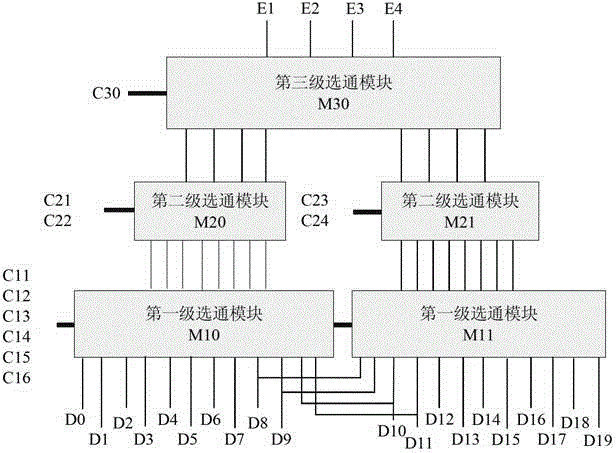
[0034] One of the first-level gating modules is connected to twelve consecutive bit lines, and two of the first-level gating modules are connected by sharing four continuous bit lines; one of the first-level gating modules is connected through eight consecutive bit lines. The secondary bit line is connected to one of the second-level gating modules; one of the second-level gating modules is connected to the third-level gating module through four main bit lines.

[0035] Each of the first-level gating modules includes six gating control signal application terminals, and multiple first-level gating modules multiplex the six gating control signal application terminals;

[0036] Each of the second-level gating modules includes two gating control signal application terminals;

[0037] Each of the third-level gating modules is controlled by one of the third-level gating control signal application t...

Embodiment 2

[0045] As a specific embodiment, this embodiment is based on the above-mentioned solution, specifically as follows: the first-level gating module includes eight tube units, each tube unit includes two to three gating tubes, and each tube unit The control signal connection ports of the strobe tubes are connected to the continuous odd bit lines or continuous even bit lines in the continuous bit lines, and each bit line is connected to the strobe tubes in a plurality of tube units; each of the first-stage strobe The module is controlled by six control signal application ends, and each control signal application end controls at least one gating tube. When multiple gating tubes can be controlled, the multiple gating tubes belong to different tube units ; The operation signal connection ports of the gate tubes in each tube unit are connected to the same secondary bit line; multiple first-level gate modules multiplex six control signal application ends, and among the multiple first-le...

Embodiment 3

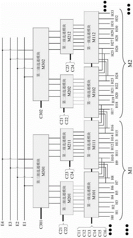
[0080] see Figure 4 , the embodiment shown is an extended multi-level bit line gating device, only two minimum expansion units are shown in the figure, and the remaining minimum expansion units are represented by ellipsis, including:

[0081] Multiple minimum expansion units: M1, M2..., each minimum expansion unit includes two first-level gating modules, two second-level gating modules, one third-level gating module, and one third-level control signal An application terminal, eight main bit lines and sixteen consecutive sub-bit lines; wherein, the third-level control signal application terminal is used to apply a gate control signal to the third-level gating module;

[0082] Ten control signal application terminals C11 to C16, C21 to C24 are used to apply bit line gating control signals generated by the decoder, among which six first-level control signal application terminals are used to apply to the first-level gating module The bit line gate control signals are respectivel...


PUM


Abstract

The embodiment of the invention provides a multilevel gating device applied in gating of bit lines of a memory array, and is applied in gating of the bit lines of the memory array. The multilevel gating device comprises multilevel gating modules, wherein first level gating modules are connected with continuous bit lines, and the two first level gating modules are connected with each other through shared bit lines; second level gating modules are respectively connected with the first level gating modules, secondary bit lines connected with the second level gating modules are independent to one another, and the second level gating modules reuse second level gating control signal applying terminals to control gating; each two adjacent second level gating modules are connected to one same third level gating module, third level gating control signal applying terminals are used for controlling gating, and each third level gating module is controlled by control signals independent to the other third level gating control modules. The multilevel gating device improves scalability of a gating device.

Description

technical field [0001] The invention relates to the field of memory, in particular to a multilevel gate device applied to memory array bit line gate. Background technique [0002] As the demand for high-density storage arrays increases, storage arrays with virtual land structures are more and more widely used in storage devices. Virtual land structure storage array see figure 1 , the memory cells cell00, cell01...cellMN of the memory array 10 are arranged in an array in the form of M rows and N columns, each memory cell includes a plurality of connection ports, and one of the connection ports is used as a control port to connect to the word line gating device, The two connection ports are respectively connected to a bit line, and the bit line is connected to the bit line gating device 11, and the bit line connection ports of each column of memory cells share the same bit line with the memory cells of adjacent columns, figure 1 The bit line connection port of the memory cel...

Claims


Application Information

Patent Timeline
Patent Type & Authority Patents(China)
IPC IPC(8): G11C7/12G11C7/18
Inventor 龙爽陈岚陈巍巍杨诗洋
Owner INST OF MICROELECTRONICS CHINESE ACAD OF SCI
Why Eureka
Try Eureka