Method for forming metal pin of switch and metal pin of switch

A molding method and switch technology, applied in the direction of electric switches, contact electrical connections, electrical components, etc., can solve the problems of easy failure and affecting the contact area of ​​balls 13, so as to improve the conduction effect, improve the simplicity and convenience, The effect of improving smoothness

Inactive Publication Date: 2014-01-15
ONCQUE CORP
View PDF5 Cites 0 Cited by
  • Summary
  • Abstract
  • Description
  • Claims
  • Application Information

AI Technical Summary

Problems solved by technology

[0006] According to the foregoing, when the metal pin 12 is assembled, it is easy to scratch the housing 11 due to the aforementioned bright band II', fracture band III' and burr IV' which are rough on the surface and occupy a large area, and form a resistance, and from a microscopic point of view, the aforementioned rough surface, especially the burr Ⅳ', will also affect the contact area with the ball 13 after assembly, and the connection is likely to fail

Method used


Image

  • Method for forming metal pin of switch and metal pin of switch
  • Method for forming metal pin of switch and metal pin of switch
  • Method for forming metal pin of switch and metal pin of switch

Examples


Embodiment Construction

[0031] The present invention will be described in detail below in conjunction with the accompanying drawings and embodiments.

[0032] refer to Figure 5 , Image 6 and Figure 8 , a first preferred embodiment of the metal pin 2 of the switch of the present invention, the metal pin 2 is elongated and includes a contact portion 201 and a connecting portion 202 extending integrally with the contact portion 201, the contact portion 201 has four 21 end angles.

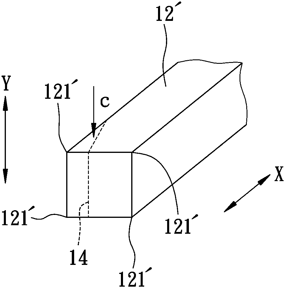
[0033] The metal pin 2 defines a long-axis direction X and a short-axis direction Y perpendicular to the long-axis direction X along the long direction, wherein the short-axis direction Y is parallel to two sides of the cross-section of the metal pin 2 , the direction perpendicular to the other two sides of the cross section.

[0034] Each end angle 21 of the aforementioned contact portion 201 is stamped and formed to form an end angle mold roll area I with a smooth arc surface, and the depth t of the end angle mold ro...


PUM


Abstract

Provided are a method for forming a metal pin of a switch and the metal pin of the switch. The switch is provided with a conducting element transmitting signals. The pin is provided with a terminal angle die roller area or a corner collapse area which is in contact with the conducting element, and the depth of the terminal angle die roller area or the depth of the corner collapse area is smaller than the depth of the section of the pin. Therefore, through a smooth face formed by the terminal angle die roller area or the corner collapse area, mounting smoothness is improved, and the conducting effect of the pin and the conducting element is improved.

Description

technical field [0001] The invention relates to a metal pin, in particular to a metal pin forming method for a switch and the metal pin. Background technique [0002] refer to figure 1 Taking the general ball switch 1 as an example, it mainly includes a housing 11, four metal pins 12 arranged in an array and partially penetrated in the housing 11, and housed in the housing 11 and located in the aforementioned metal pins 12. A ball 13 between pins 12. [0003] Under normal use conditions, the ball 13 will contact the aforementioned metal pins 12 at the same time to form a conduction loop and be in the "ON" state. When the metal pin 12 is connected, it will form an open circuit and be in the "OFF" state, thereby achieving the effect of "ON / OFF" on and off control. [0004] refer to figure 1 ,and figure 2 , image 3 , Figure 4 Generally, when the metal pin 12 is manufactured, a material 12' with a rectangular cross-section and extending along a long axis direction X is...

Claims


Application Information

Patent Timeline
Patent Type & Authority Applications(China)
IPC IPC(8): H01H11/00H01H1/58
Inventor 周添铭
Owner ONCQUE CORP
Why Eureka
Try Eureka