
Micro instrument terminal based on module joint and used for minimally invasive surgery robot
A surgical robot and minimally invasive surgery technology, applied in the field of minimally invasive surgical robot medical equipment, can solve the problems of reducing the reliability and safety of surgical instruments, inflexible layout of degrees of freedom, increasing design costs, etc., and achieving easy assembly. , Large clamping force, the effect of increasing the size of the wire rope
- Summary
- Abstract
- Description
- Claims
- Application Information
AI Technical Summary
Problems solved by technology
Method used
Image

Examples
Embodiment approach
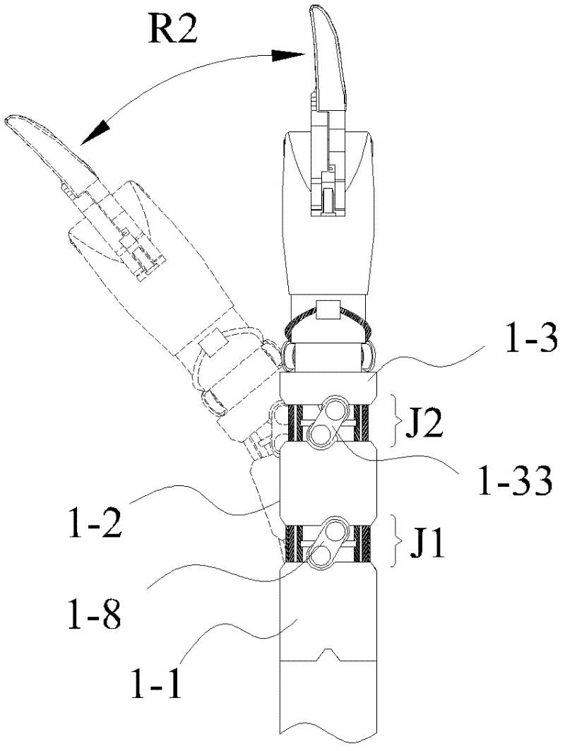
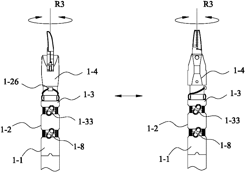
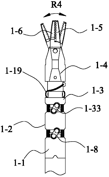
[0026]A microinstrument terminal for a minimally invasive surgical robot based on modular joints of the present invention includes a module bottom part 1-1, and a module top part 1-2 and a rotating connection shaft 1 are sequentially arranged above the module bottom part -3, upper arc grooves 1-20 are respectively opened on the top surfaces of the module bottom part 1-1 and the module top part 1-2, and lower arc grooves are respectively opened on the bottom surface of the module top part and the bottom surface of the rotating connecting shaft Arc groove 1-18, on the module bottom part 1-1, top part 1-2 and rotating connecting shaft 1-3 on the left and right sides of each upper arc groove 1-20 and lower arc groove 1-18 The left and right connecting seats with connecting holes 1-22 are arranged respectively, and the axis of each upper and lower arc groove 1-20 is parallel to the axes of the connecting holes 1-22 on the left and right connecting seats on both sides thereof. Offse...
PUM
 Abstract
Description
Claims
Application Information