Overvoltage protection device having at least one surge arrester

A technology of overvoltage protection device and discharger, which is applied in the direction of overvoltage protection resistor, emergency protection device with automatic disconnection, emergency protection circuit device, etc., and can solve the fire, danger and discharger of the explosive equipment itself or adjacent devices Damage and other problems, to achieve the effect of improving self-extinguishing ability

Active Publication Date: 2014-01-15
DEHN SOHNE GMBH CO KG
View PDF8 Cites 12 Cited by
  • Summary
  • Abstract
  • Description
  • Claims
  • Application Information

AI Technical Summary

Problems solved by technology

[0010] The disadvantage of combining an overvoltage protective device with a fuse or a mechanical switchgear is that a short-circuit current in the sense of several times the nominal current of the switchgear or fuse must always flow when these elements react or trigger
[0011] Currents, typically in the hundreds of amperes or into the kiloampere range, can cause voltage limiting components to fail or explode and become a fire hazard to the equipment itself or adjacent installations
[0012] Thus, if the fault current occurring in the overvoltage protection device is greater than the fault current that can be eliminated by the thermal disconnection device itself but less than the trigger current of the backup protection device (such as a fuse device), the arrester may be damaged by the above-mentioned consequences. damaged

Method used


Image

  • Overvoltage protection device having at least one surge arrester
  • Overvoltage protection device having at least one surge arrester
  • Overvoltage protection device having at least one surge arrester

Examples


Embodiment Construction

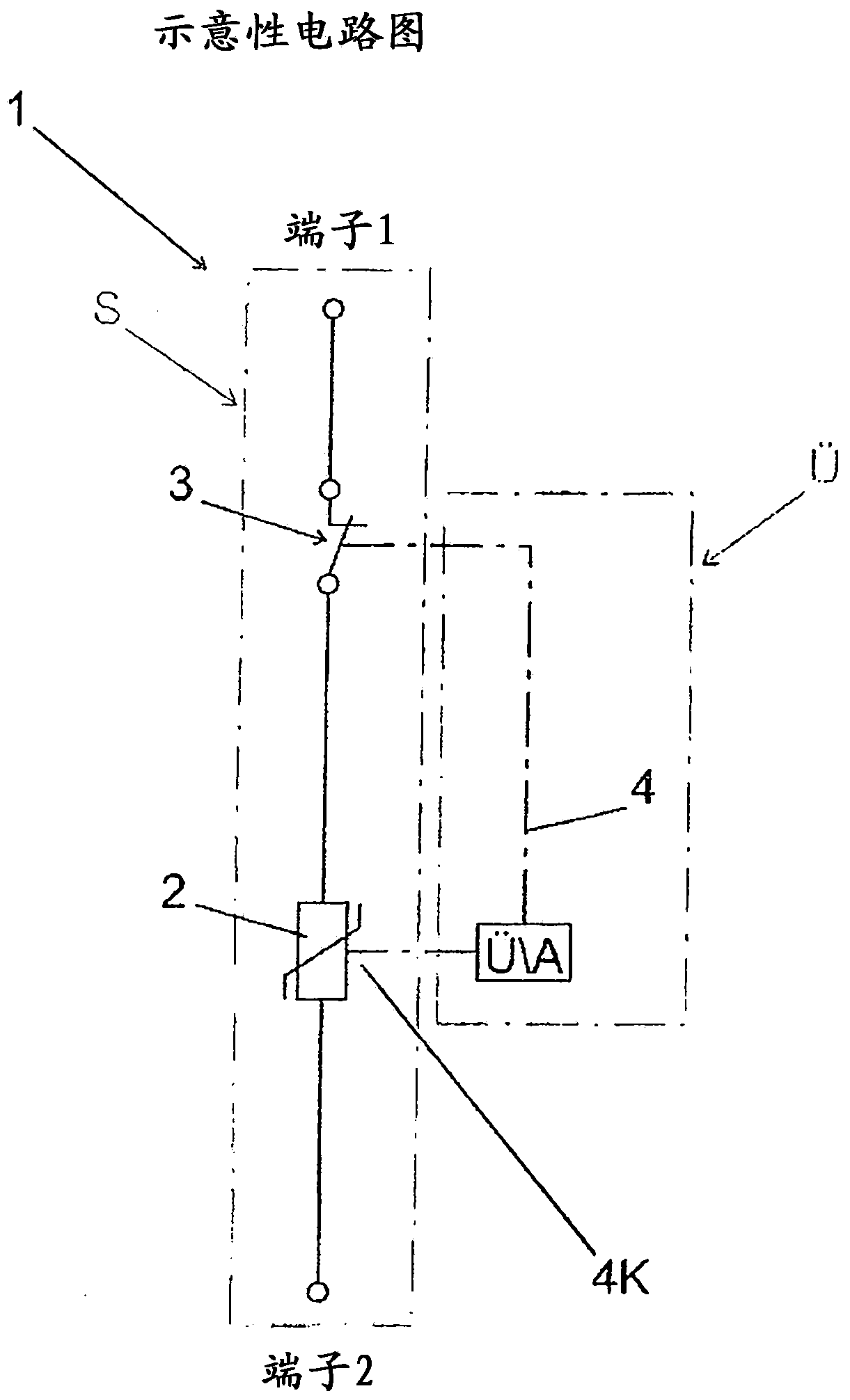
[0044] according to Figure 1a The illustration of the schematic circuit diagram is based on the overvoltage protection mechanism 1, where the working surge current path S and the monitoring path functionally separated. The integrated switching device 3 has extended self-switching and self-extinguishing capabilities, the reference number 2 designating a surge arrester, for example designed as a varistor. with reference number 4 in Figure 1a The unlocking device of the switching device 3 is symbolized in , while the thermal coupling element as a thermal triggering mechanism is indicated in 4K.

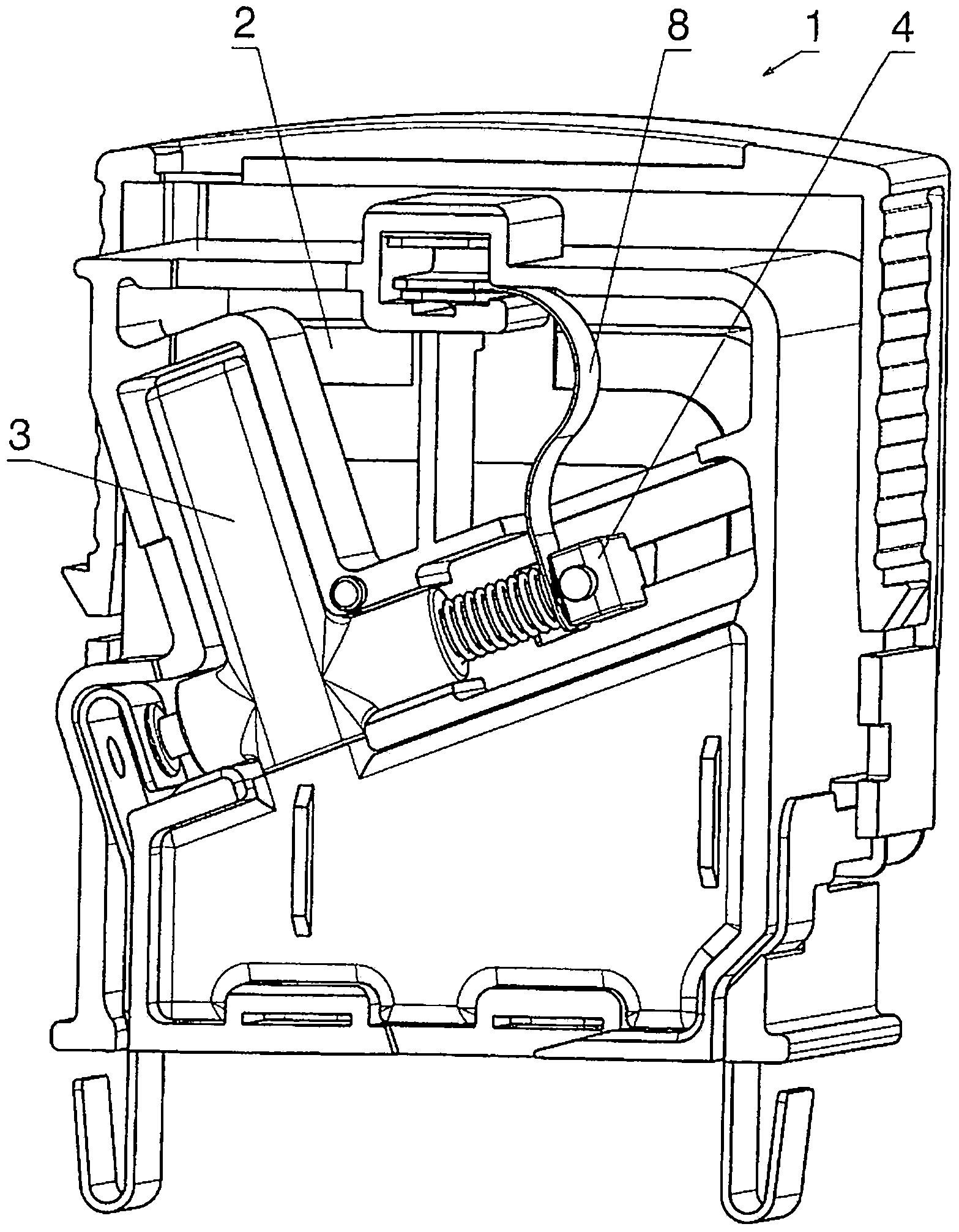
[0045] The plug connector realized according to the invention comprises a surge protection device 1 with a surge arrester 2 , a release slide 4 and a molded body 3 which accommodates the switching device. Furthermore, there are plug contacts for supplying the operating current on the underside of the plug connector. according to Figure 1b The reference number 8 designates a movable...


PUM


Abstract

The invention relates to an overvoltage protection device, comprising at least one surge arrester and one switchgear assembly, which is connected in series to the surge arrester and which can be triggered thermally, wherein the aforementioned components form a structural unit, and the thermal tripping means is arranged in the area of the expected heating up of the surge arrester when overloaded. According to the invention, the thermal tripping unit is configured as a stop element through which operating current or surge current does not flow. In the event of thermal overload, the stop element opens a releasing device of the switchgear assembly, wherein said switchgear assembly has an increased self-extinguishing capacity.

Description

technical field [0001] The invention relates to an overvoltage protection device according to the preamble of claim 1 , comprising at least one surge arrester and a thermally triggerable switching device connected in series with the surge arrester, wherein the The described mechanism forms a structural unit and the thermal triggering mechanism is arranged in the region where the surge arrester is expected to generate heat when it is overloaded. Background technique [0002] DE 29519313 U1 discloses a varistor-based surge arrester which is responsible for transferring the heat that develops at the varistor in the event of damage directly to the thermal trigger. For this purpose, a support wall is present in the plug connector, wherein the varistor is arranged on one side of the support wall and the thermal trigger with its associated switching mechanism is arranged on the other side of the support wall. Thus, the thermal trigger part faces the piezoresistor. In one refineme...

Claims


Application Information

Patent Timeline
Patent Type & Authority Applications(China)
IPC IPC(8): H01C7/12H01H37/00
CPCH01C7/12H01C7/126H01H1/14H01H83/10H01T1/14H02H3/085
Inventor H·希尔施曼G·维特曼E·策纳
Owner DEHN SOHNE GMBH CO KG
Why Eureka
Try Eureka