A post-treatment process for the surface of sls parts
A technology of parts and processes, which is applied in the field of SLS parts surface post-treatment technology, can solve the problems of surface roughness, smoothness and coloring that cannot meet the requirements of use, and achieve the effect of improving the optimization rate
- Summary
- Abstract
- Description
- Claims
- Application Information
AI Technical Summary
Problems solved by technology
Method used
Image
Examples
Embodiment 1
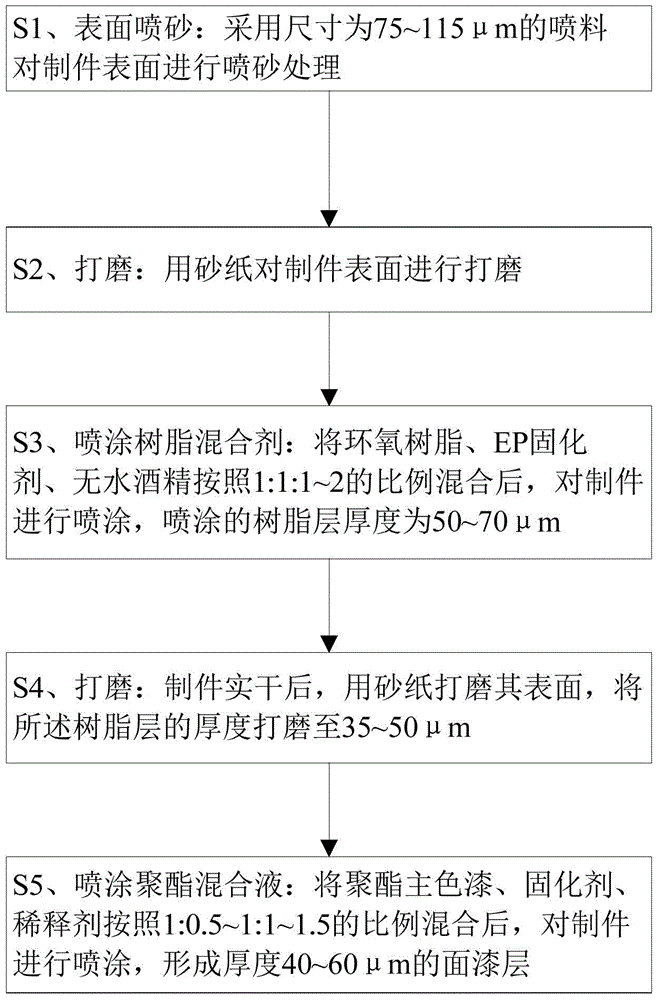
[0033] Select the flat plate workpiece P1 obtained by sintering with the SLS rapid prototyping system, and process it according to the following steps:
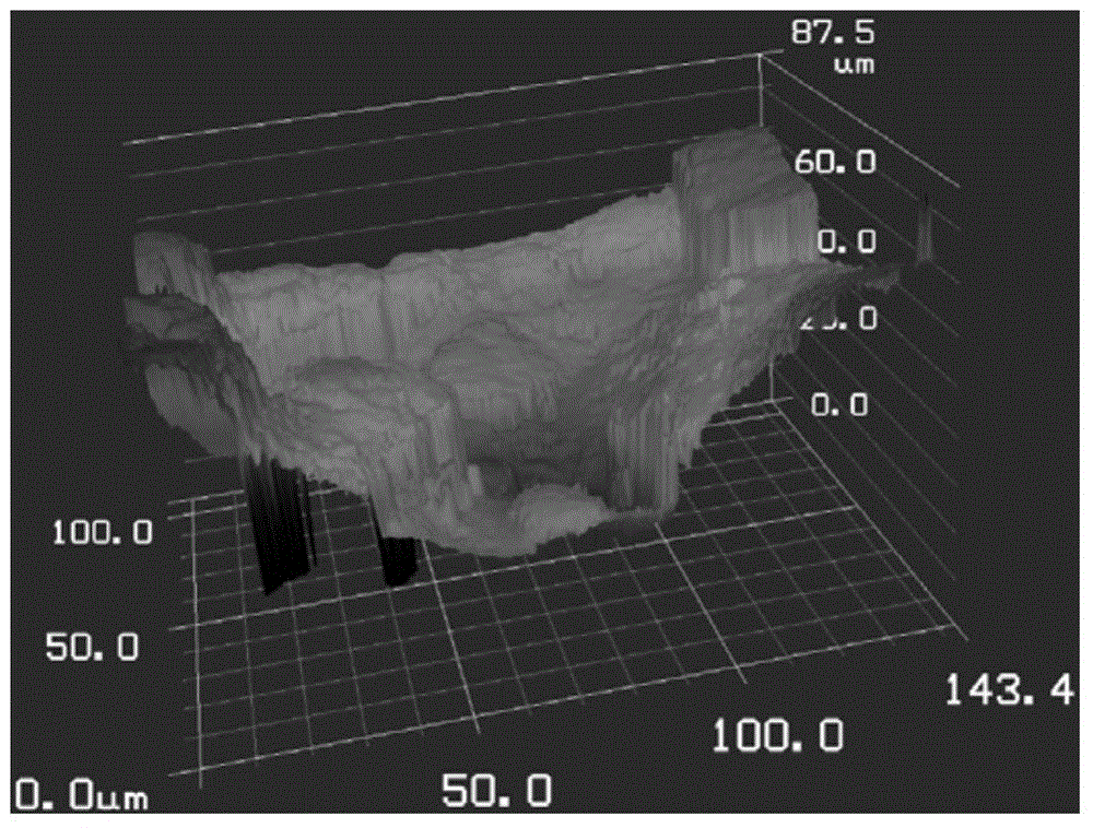
[0034] S1. Sandblasting: Spray glass sand with a size of 150 mesh (equivalent to 106μm) through a sandblasting machine, and perform sandblasting treatment on the surface of P1 to clean off the powder attached to the surface, and at the same time, impact and grind the burrs on the surface , making it slightly deformed, eliminating the residual stress after processing, and obtaining a workpiece with a roughness of Ra11.39, the effect diagram is as follows figure 2 shown;
[0035] S2. Grinding: For the flat processed part P1 after sandblasting, first use No. 180 sandpaper to polish, and then use No. 360 sandpaper to polish until the surface of the flat processed part P1 feels smooth;
[0036] S3. Spraying resin mixture: mix epoxy resin, EP curing agent, and absolute alcohol in a ratio of 1:1:1, let it stand for 10 minutes, and...
Embodiment 2
[0043] Select the flat plate workpiece P2 sintered by the SLS rapid prototyping system, and process it according to the following steps: Compared with Example 1, steps S1 and S2 are the same, and the initial roughness of P2 is also Ra11.39. The difference in processing is:
[0044] S3. Spraying resin mixture: mix epoxy resin, EP curing agent, and absolute alcohol in a ratio of 1:1:2, let it stand for 15 minutes, and spray the flat plate P2 in a cross method, first along a certain After spraying in the X direction alone, spray in the Y direction perpendicular to the X direction, and then surface dry for 10 minutes. The thickness of the sprayed surface resin layer is 50 μm;
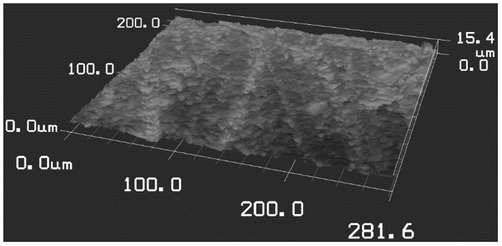
[0045] S4. Grinding: After the plate processing part P2 is dry, polish its surface with No. 360 sandpaper, polish the burrs not covered by the resin layer, and polish the thickness of the surface resin layer to 40 μm. The surface roughness at this time is Ra1.48 , its effect is as follows Figure 4 shown; ...
Embodiment 3
[0050] The difference between the present embodiment and the embodiment 1 is only that the size of the sandblasting material in step S1 is 75 μm. It is proved by experiments that the present embodiment can also obtain substantially the same effect as the embodiment 1.
PUM
| Property | Measurement | Unit |
|---|---|---|
| thickness | aaaaa | aaaaa |
| thickness | aaaaa | aaaaa |
| thickness | aaaaa | aaaaa |
Abstract
Description
Claims
Application Information
 - R&D
- Intellectual Property
- Life Sciences
- Materials
- Tech Scout
- Unparalleled Data Quality
- Higher Quality Content
- 60% Fewer Hallucinations
Browse by: Latest US Patents, China's latest patents, Technical Efficacy Thesaurus, Application Domain, Technology Topic, Popular Technical Reports.
© 2025 PatSnap. All rights reserved.Legal|Privacy policy|Modern Slavery Act Transparency Statement|Sitemap|About US| Contact US: help@patsnap.com


