
Yarn dyeing machine

A yarn dyeing machine and dye vat technology, applied in the field of yarn dyeing machines, can solve the problems of insufficient adaptability, uneven yarn dyeing and the like

Active Publication Date: 2015-06-03
WUJIANG KESHIDA TEXTILE
View PDF6 Cites 1 Cited by
  • Summary
  • Abstract
  • Description
  • Claims
  • Application Information

AI Technical Summary

Problems solved by technology

In the prior art, there is equipment for single-thread dyeing of yarns, which can avoid the problem of uneven dyeing of yarns caused by piled yarns. However, different yarns and dyeing solutions have their own different characteristics, and the dyeing process is also required. not exactly
The equipment in the prior art is fixed for the walking path of the yarn in the dyeing vat, so the adaptability of the equipment to specific conditions is very insufficient

Method used

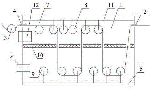

Image

  • Yarn dyeing machine
  • Yarn dyeing machine

Examples


Embodiment Construction

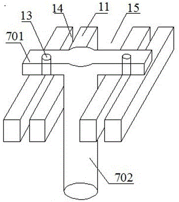
[0016] Such as figure 1 As shown, a yarn dyeing machine of the present invention includes a dyeing vat 1, a liquid inlet 5 arranged on the side wall of the dyeing vat 1, a liquid outlet 6 arranged at the bottom of the dyeing vat 1, and an inlet port 6 arranged on the side wall of the dyeing vat 1. Yarn port 2 and the yarn outlet port 4 located on the opposite side of the yarn inlet port 2; the top of the inner wall of the dyeing vat 1 is provided with a yarn draining roller 8, and the bottom of the inner wall of the dyeing vat 1 is provided with a yarn dyeing roller 9; The yarn roller 9 is movably connected to the support member 7, the support member 7 is composed of a support member transverse portion 701 and a support member shaft portion 702, and the support member transverse portion 701 is provided with a through hole 13; the dye vat 1 is close to the top The position of crossbeam 11 is provided, and the two ends of crossbeam 11 are fixedly connected on the inner wall of d...


PUM


Abstract

The invention relates to textile dyeing equipment, in particular to a yarn dyeing machine. The yarn dyeing machine comprises a dye vat, a liquid inlet formed in the lateral wall of the dye vat, a liquid outlet formed in the bottom of the dye vat, a yarn inlet formed in the lateral wall of the dye vat and a yarn outlet formed in the opposite side of the yarn inlet, wherein a yarn draining roller is arranged at the top of the inner wall of the dye vat, a yarn dyeing roller is arranged at the bottom of the inner wall of the dye vat, the yarn draining roller and the yarn dyeing roller are movably connected to a supporting part, the supporting part is composed of a supporting part transverse part and a supporting part shaft part, the supporting part transverse part is provided with through holes, a cross beam is arranged in the position, near the top, of the dye vat, the two ends of the cross beam are fixedly connected to the inner wall of the dye vat, a slideway matched with the supporting part shaft part is arranged in the middle of the cross beam, through grooves are formed in the cross beam at the two sides of the slideway, and the through holes in the supporting part transverse part and the through grooves in the cross beam are of a mutually matched structure. After the structure is adopted, dyeing at the best extent can be carried out, the quality of finished products is guaranteed, and dyeing efficiency is largely improved.

Description

technical field [0001] The invention relates to a textile dyeing device, in particular to a yarn dyeing machine. Background technique [0002] Yarn coloring is the prerequisite for yarn to be spun and various finished products can be spun, and the quality of coloring directly affects the sales of finished products. In the prior art, there is equipment for single-thread dyeing of yarns, which can avoid the problem of uneven dyeing of yarns caused by piled yarns. However, different yarns and dyeing solutions have their own different characteristics, and the dyeing process is also required. not exactly. The equipment in the prior art is fixed for the walking path of the yarn in the dyeing vat, so the adaptability of the equipment to specific conditions seems very insufficient. Contents of the invention [0003] The technical problem to be solved in the present invention is to provide a yarn dyeing machine, which can automatically adjust the walking path of the yarn in th...

Claims


Application Information

Patent Timeline
Patent Type & Authority Patents(China)
IPC IPC(8): D06B3/06D06B23/20D06B23/22
CPCD06B3/06
Inventor 庄郁峰范丽恒李琼
Owner WUJIANG KESHIDA TEXTILE
Learn More