Simply supported box girder with corrugated steel web and steel-concrete composite structure

A corrugated steel web and composite structure technology, used in bridges, bridge parts, bridge construction, etc., can solve problems such as inability to cooperate with force, stress concentration, stress redistribution, etc., achieve good structural performance and economy, and improve strength. Effect

Active Publication Date: 2015-10-14
ZHEJIANG CTB WAVEFORM STEEL WEB
View PDF6 Cites 0 Cited by
  • Summary
  • Abstract
  • Description
  • Claims
  • Application Information

AI Technical Summary

Problems solved by technology

[0003] The invention aims at the disadvantages of poor shear resistance and buckling resistance of ordinary box girders in the prior art, and the corrugated steel webs of box girders are prone to stress concentration, resulting in short service life of box girders, etc., especially in composite structures. The shrinkage and creep characteristics make it unable to cooperate with the steel structure, resulting in stress redistribution
Provides a way to increase the cross-sectional rigidity of the beam body and the strength of the connection end by setting the end plate of the head. The waveform of the web is composed of three parts: a straight line section, a transition section, and an arc section, and the transition section can effectively connect the straight line section. And the arc section, solve the problem of stress concentration when the straight line section and the arc section are directly connected, and at the same time use the steel and concrete composite structure with micro-strain waves as the pressure-bearing structure, which has the advantage of high cost performance, forming corrugated steel web steel Mixed Composite Structure Simply Supported Box Girder

Method used


Image

  • Simply supported box girder with corrugated steel web and steel-concrete composite structure
  • Simply supported box girder with corrugated steel web and steel-concrete composite structure
  • Simply supported box girder with corrugated steel web and steel-concrete composite structure

Examples


Embodiment 1

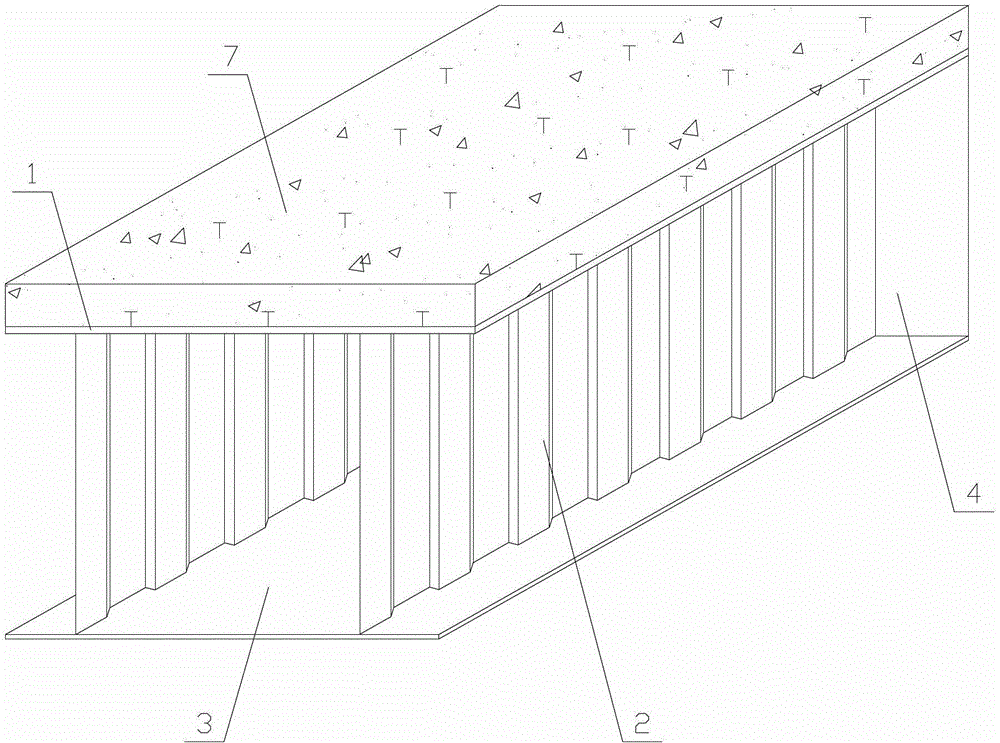
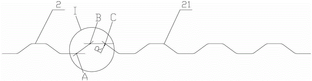
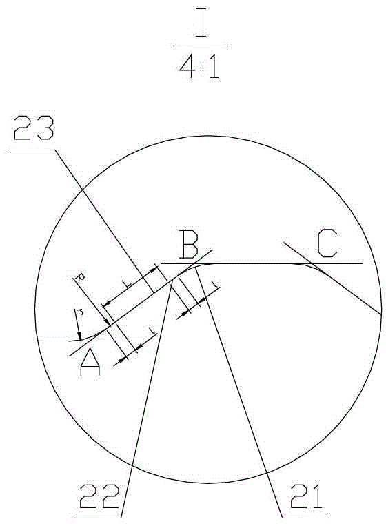
[0030] Simple supported box girder with corrugated steel web and steel-concrete composite structure, Figure 1 to Figure 7 , 8, 9 include two or more corrugated steel webs 2, top steel plate 1, concrete 7, bottom steel plate 3 and head end plate 4, characterized in that: the corrugated steel web 2 is set on the top steel plate 1 and Between the bottom steel plates 3, the top steel plate 1 and the corrugated steel web 2 are connected by welding, and the corrugated steel web 2 and the bottom steel plate 3 are connected by welding. The surface roughness of the top steel plate 1 and the bottom steel plate 3 is 70-350 μm. The top steel plate 1 or the bottom steel plate 3 and the concrete 7 are combined to form a concrete composite structure. When the simply supported box girder is an ordinary beam, the top steel plate 1 is mainly subjected to pressure. At this time, the top steel plate 1 and concrete 7 are combined to form a concrete composite structure; when the simply supported box...

Embodiment 2

[0040] Such as Figure 1 to Figure 5 , 7, 8, and 9, the difference between this embodiment and embodiment 1 is that: one end of the simply supported box beam is provided with a plug 24, and the other end is provided with a socket 25, and the plug 24 is passed between adjacent simply supported box beams. It is matched with the jack 25, the plug 24 is provided with a barb, and the jack 25 is concave. The thickness of the top steel plate 1 is smaller than the thickness of the bottom steel plate 3. At this time, the bottom steel plate 3 serves as a pressure bearing surface, and its main structure is a cantilever box beam.

[0041] The top steel plate 1 has a micro strain wave 11 with a convex wave crest. The wave height of the micro strain wave 11 is 3-20 times the thickness of the top steel plate, the peak length of the convex part is 250mm, and the distance between the wave crest and the wave crest is 1500mm. In this embodiment, the wave height of the micro strain wave is 10 tim...


PUM


Abstract

The invention relates to a box girder, and discloses a corrugated steel web reinforced concrete combination structure simply-supported box girder. The corrugated steel web reinforced concrete combination structure simply-supported box girder comprises two or more corrugated steel webs, a top steel plate, concrete, a bottom steel plate and an end sealing end plate. The corrugated steel webs are arranged between the top steel plate and the bottom steel plate, the top steel plate, the bottom steel plate and the corrugated steel webs are connected in a welded mode, and a concrete combination structure is formed by the top steel plate or the bottom steel plate and the concrete in a combined mode. According to the corrugated steel web reinforced concrete combination structure simply-supported box girder, the end sealing end plate is arranged, and therefore the strength of the cross section of a girder body and the strength of the connecting end are improved. Due to the arrangement of three transition sections of the corners of the corrugated steel webs, smooth transition between linear sections and arc sections can be achieved, the problem of stress concentration of the corners is solved, the phenomenon that the girder body of an overload vehicle falls off or the girder body falls off under the effect of large loads or earthquakes can be effectively prevented through the connection and discontinuous structure, particularly, the steel concrete combination structure with miniature strain waves is adopted in pressure-bearing portions, and the good structural performance and the good economical efficiency are achieved.

Description

Technical field [0001] The invention relates to a box girder, in particular to a simple-supported box girder of a corrugated steel web steel-concrete composite structure. Background technique [0002] At present, the traditional I-beam or steel box girder requires shear buckling resistance. The height-to-thickness ratio of the web is generally around 100:1. The trapezoidal corrugated steel web is thick due to its strong shear and buckling performance. The ratio is 300:1. The corrugated steel webs used in the existing corrugated steel web box girder, the waveforms of the webs are all composed of straight line segments and circular arc segments, and stress concentration is likely to occur at the connection part of the straight line segment and the circular arc segment. The compression flange of traditional I-beam or steel box girder also adopts steel plate. The use of steel structure in the compression zone cannot reflect the economy of steel structure. For example, a steel-concre...

Claims


Application Information

Patent Timeline
Patent Type & Authority Patents(China)
IPC IPC(8): E01D19/00E01D2/04
Inventor 孙天明高波
Owner ZHEJIANG CTB WAVEFORM STEEL WEB
Why Eureka
Try Eureka