Simply supported I beam adopting corrugated steel web steel structure

A corrugated steel web and steel structure technology, applied in truss structures, joists, girders, etc., can solve problems such as stress concentration and discontinuity, and achieve the effects of solving stress concentration, improving strength, and preventing beams from falling.

Active Publication Date: 2013-12-04
HANGZHOU BOSHU CIVIL ENG TECH
View PDF8 Cites 2 Cited by
  • Summary
  • Abstract
  • Description
  • Claims
  • Application Information

AI Technical Summary

Problems solved by technology

[0003] The present invention aims at the disadvantages of simply supported I-beams with corrugated steel webs that are prone to stress concentration and the like in the prior art, and provides a method of improving the cross-sectional rigidity of the beam body and the strength of the connecting end by setting the end plate of the head, and the waveform of the web is improved. It is composed of three parts: straight line section, transition section, and arc section. The transition section can effectively connect the straight line section and the arc section to solve the problem of stress concentration when the straight line section and the arc section are directly connected. Conjoined and discontinuous structure, effectively prevent the beam from falling under the action of overloaded vehicles and large loads or earthquakes. Simply supported I-beams with corrugated steel webs

Method used


Image

  • Simply supported I beam adopting corrugated steel web steel structure
  • Simply supported I beam adopting corrugated steel web steel structure
  • Simply supported I beam adopting corrugated steel web steel structure

Examples


Embodiment 1

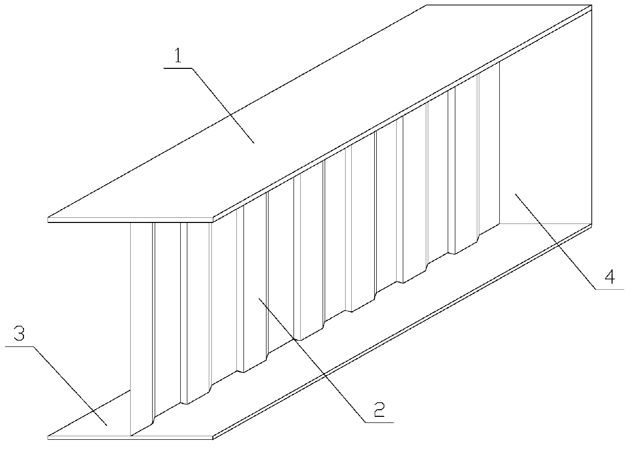
[0026] Corrugated steel web steel structure simply supported I-beam, such as Figure 1 to Figure 6 As shown, the beam body includes a corrugated steel web 2, an upper flange steel plate 1, a lower flange steel plate 3, and a head end plate 4. The corrugated steel web 2 is arranged on the upper flange steel plate 1 and the lower flange Between the steel plates 3, the upper flange steel plate 1 and the corrugated steel web 2 are connected by welding, and the corrugated steel web 2 and the lower flange steel plate 3 are connected by welding.

[0027] The surface roughness of the upper flange steel plate 1 and the lower flange steel plate 3 is 70-350 μm. Increase the surface roughness of the upper flange steel plate 1 and the lower flange steel plate 3, high roughness can significantly increase the adhesion of the coating.

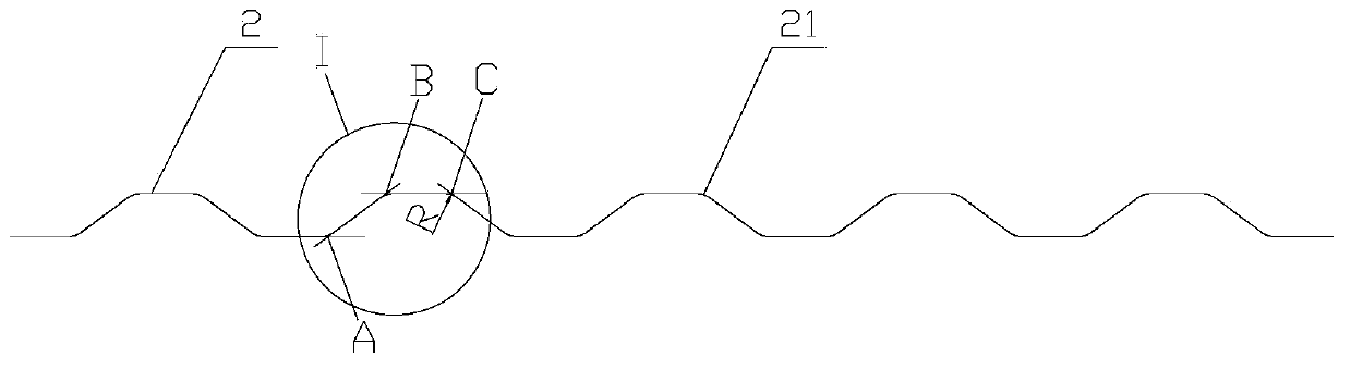
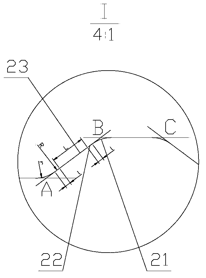
[0028] The corrugated steel web 2 is a continuous trapezoidal corrugated steel plate with a transition section 22 and an arc corner 21. The transition sectio...

Embodiment 2

[0036] Such as Figure 1 to Figure 5 , 7, the difference between this embodiment and embodiment 1 is: the plug 24 is provided with a barb, and the jack 25 is concave. The thickness of the upper flange steel plate 1 is smaller than the thickness of the lower flange steel plate 3 . At this time, the lower flange steel plate 3 is used as the bearing surface, and its main structural form is a cantilever beam.


PUM


Abstract

The invention relates to an I beam, and discloses a simply supported I beam adopting a corrugated steel web steel structure. A beam body includes a corrugated steel web (2), a top flange steel plate (1), a bottom flange steel plate (3), and a gland end plate (4), wherein the corrugated steel web (2) is arranged between the top flange steel plate (1) and the bottom flange steel plate (3); the top flange steel plate (1) is connected with the corrugated steel web (2) through welding; the corrugated steel web (2) is connected with the bottom flange steel plate (3) through welding. The arranged gland end plate improves the rigidity of a cross section and strength of a connecting end of the beam body, and wave forms of the web include three parts, namely the straight line section, the transitional section and the arc section, the transitional section can be used for effectively connecting the straight line section with the arc section, thereby solving the problem of stress concentration during the direct connection of the straight line section and the arc section; besides, the simply supported beams adopt a connected and discontinuous structure, thereby effectively preventing the beam body from falling off under the actions of overloaded vehicles and big loads or under the earthquake action.

Description

technical field [0001] The invention relates to an I-beam, in particular to a simply-supported I-beam with a corrugated steel web plate steel structure. Background technique [0002] For traditional I-beams or steel box girders, the height-to-thickness ratio of the web is generally about 100:1 according to the requirements of shear buckling resistance. The height-thickness ratio of the trapezoidal corrugated steel web can be Up to 300:1 and above. For the corrugated steel web used in the existing corrugated steel web I-beam, the corrugation of the web is composed of a straight line segment and an arc segment, and stress concentration is likely to occur at the connecting part of the straight line segment and the arc segment. Contents of the invention [0003] The present invention aims at the disadvantages of simply supported I-beams with corrugated steel webs that are prone to stress concentration and the like in the prior art, and provides a method of improving the cross...

Claims


Application Information

Patent Timeline
Patent Type & Authority Applications(China)
IPC IPC(8): E04C3/07E01D19/00E01D2/00
Inventor 孙天明余冬华
Owner HANGZHOU BOSHU CIVIL ENG TECH
Why Eureka
Try Eureka