Laser bonding method

A bonding and laser technology, applied in the field of laser bonding, can solve problems such as poor bonding effect, cracks, and stress accumulation of laser bonding methods

Active Publication Date: 2014-01-22
SHANGHAI UNIV
View PDF4 Cites 8 Cited by
  • Summary
  • Abstract
  • Description
  • Claims
  • Application Information

AI Technical Summary

Problems solved by technology

[0003] However, the bonding effect of this closed laser bonding method is not good, especially when the laser enters the glass device and irradiates the coincidence of the starting point and the ending point of the glass frit, t...

Method used


Image

  • Laser bonding method
  • Laser bonding method
  • Laser bonding method

Examples


Embodiment Construction

[0028] In order to make the object, technical solution and advantages of the present invention clearer, the present invention will be further described in detail below in conjunction with the accompanying drawings and embodiments. It should be understood that the specific embodiments described here are only used to explain the present invention, not to limit the present invention.

[0029] In order to better illustrate the features of this solution, laser bonding of OLED glass substrates is taken as an example below, but this is not intended to further limit the present invention.

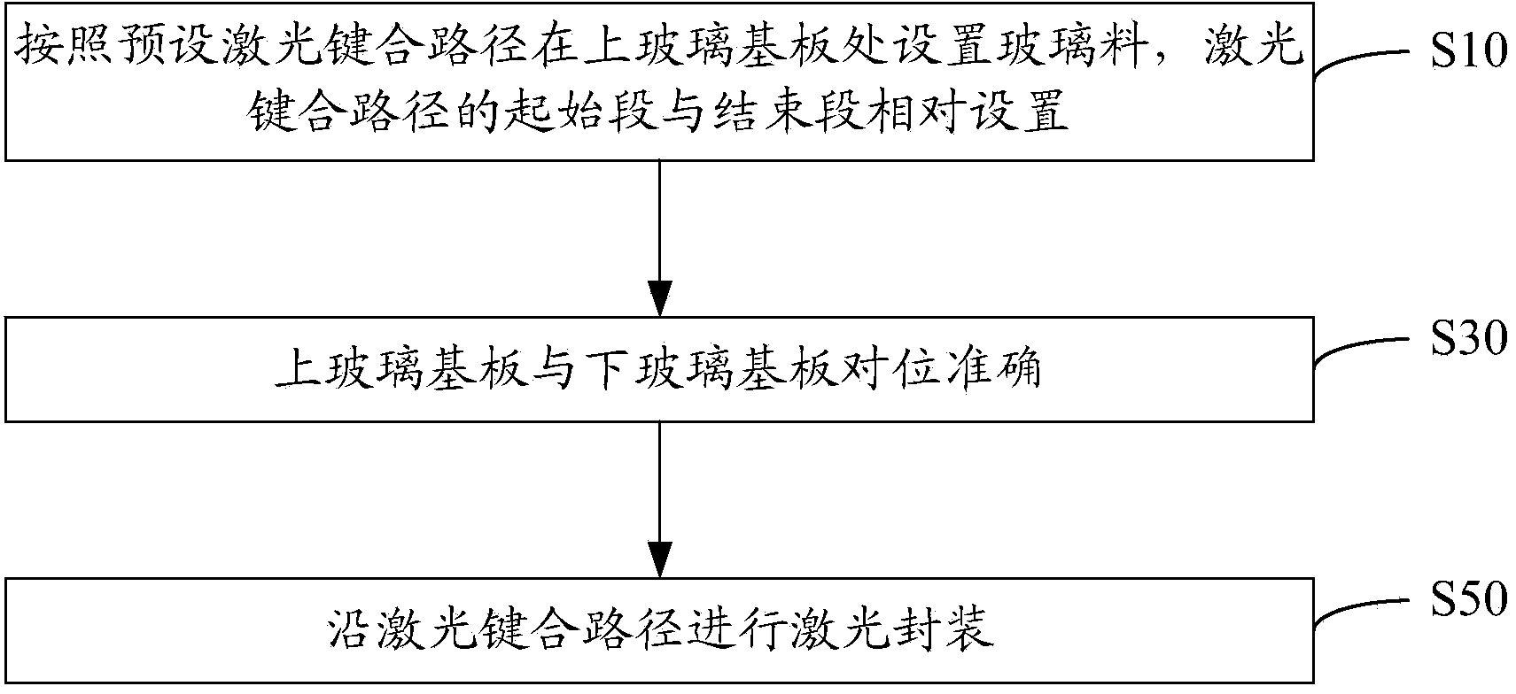
[0030] See attached Figure 1-8 , a laser bonding method, comprising the steps of:

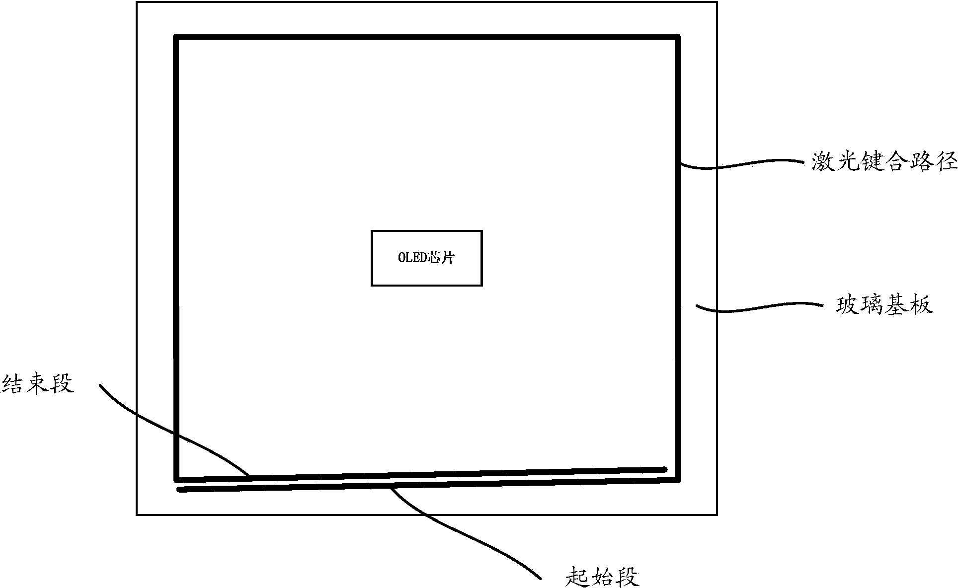
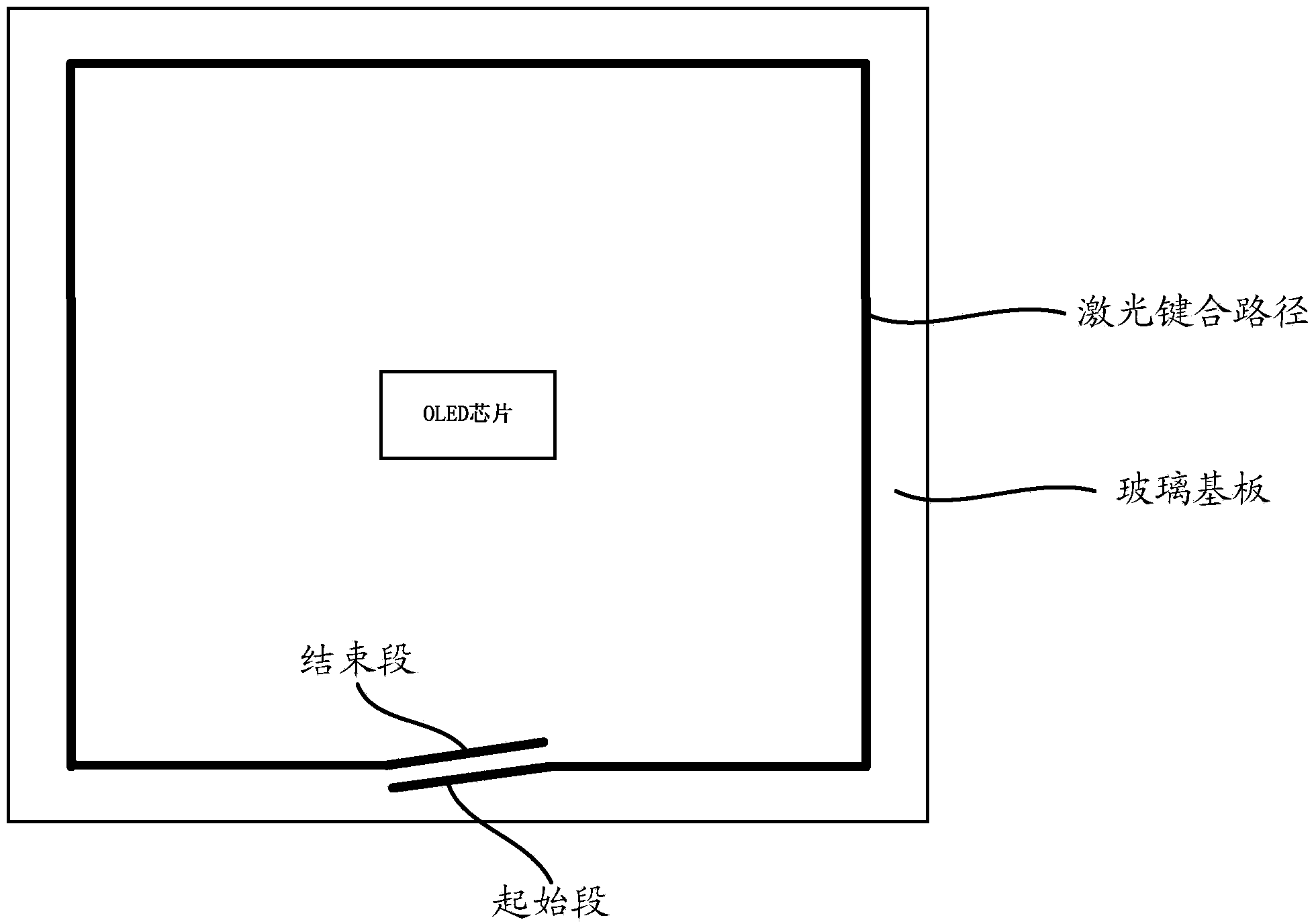
[0031] S10: setting the glass frit at the upper glass substrate according to the preset laser bonding path, and setting the start section and the end section of the laser bonding path opposite to each other.

[0032] Specifically, the laser encapsulation of the OLED glass substrate is the sealing of the upper gla...


PUM


Abstract

A laser bonding method comprises the steps as follows: a frit is arranged in the position of an upper glass substrate according to a preset laser bonding path, wherein a starting section and an ending section of the laser bonding path are arranged oppositely; the upper glass substrate and a lower glass substrate are aligned accurately; and laser encapsulation is conducted along the laser bonding path. With the adoption of the method, the starting section and the ending section of the frit are staggered and arranged oppositely, by the aid of the mobility of the frit in a fused state, the starting section is attached to the ending section, and the starting section and the ending section are attached in a 'line-line' manner instead of closed in a 'point-point' manner, so that the sealing performance of the upper and lower glass substrates can be improved.

Description

technical field [0001] The invention relates to laser packaging technology, in particular to a laser bonding method. Background technique [0002] With the development of technology, OLED packaging technology has developed from glue packaging to the current laser packaging. The traditional OLED laser packaging technology is roughly: in the process of laser scanning glass frit, the laser beam scans the glass frit printed on the substrate on the glass device for one cycle, because the glass frit pattern is ring-closed, in order for the glass device to be better under the laser irradiation Therefore, when the laser beam scans the glass frit pattern, the path of the laser beam must also be closed. [0003] However, the bonding effect of this closed laser bonding method is not good, especially when the laser enters the glass device and irradiates the coincidence of the starting point and the ending point of the glass frit, the overlapping of the starting point and the ending poi...

Claims


Application Information

Patent Timeline
IPC IPC(8): H01L51/56H01L21/56
CPCH10K71/821H10K71/00
Inventor 张建华付奎葛军锋
Owner SHANGHAI UNIV
Why Eureka
Try Eureka