Check patentability & draft patents in minutes with Patsnap Eureka AI!

card connector

A card connector and card-shaped body technology, applied in the direction of connection, clamping/spring connection, parts of the connecting device, etc., can solve the problem of accidental discharge of the card-shaped body, etc.

Inactive Publication Date: 2016-12-28
SMK CO LTD
View PDF7 Cites 0 Cited by
  • Summary
  • Abstract
  • Description
  • Claims
  • Application Information

AI Technical Summary

Problems solved by technology

[0007] However, in the above-mentioned conventional technology, since the sliding block moves in conjunction with the push-in action of the card-shaped body, the restricting pin part circulates in the pin guide groove accordingly, thereby performing the movement restriction of the slider and the release of the movement restriction. , when the card-like body is inserted in the state where the electronic device is dropped, accidentally touched, etc., and a load is applied to the card-shaped body in the direction of card insertion, there is a possibility that the card-shaped body moves due to the load, The slider moves with the card-shaped body, and the restriction pin is guided to the pin guide groove in conjunction with the movement of the slider, and at the same time disengages from the heart-shaped cam, thereby releasing the restriction on the movement of the slider in the push-out direction, causing the card-shaped body to was accidentally ejected

Method used


Image

  • card connector
  • card connector
  • card connector

Examples


Embodiment Construction

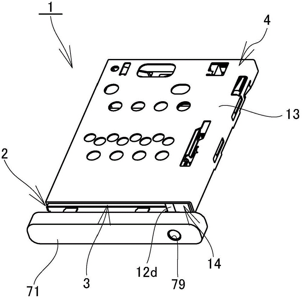
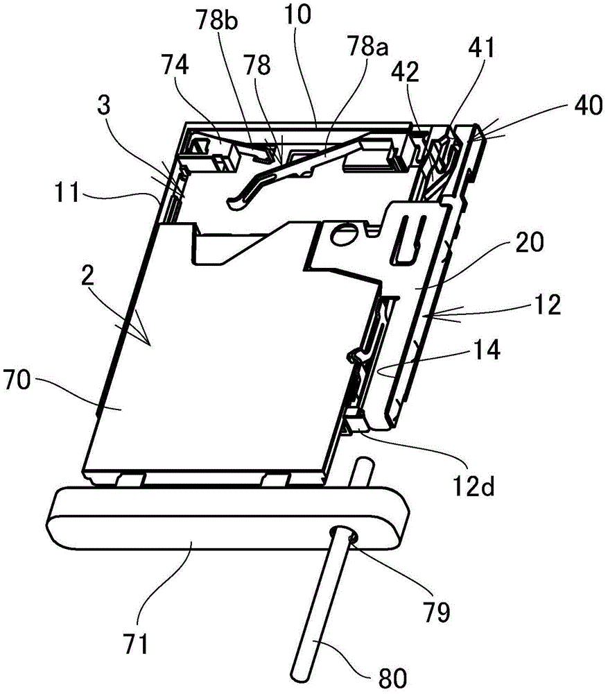
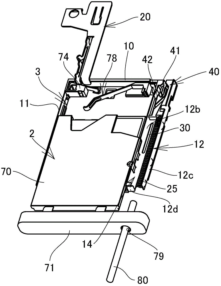
[0030] Next, based on Figure 1 to Figure 10 The illustrated embodiment illustrates an implementation of the card connector to which the present invention relates. In addition, reference numeral 1 in the figure is a card connector, and reference numeral A is a card such as an IC card.

[0031] The card connector 1 is provided with a card-like body 2, a housing 4 and a plurality of contacts 5, 5..., the card-like body 2 is composed of a card tray for accommodating a card A, and the housing 4 has a The card-shaped body insertion part 3 of the card-shaped body insertion part 3, the plurality of contacts protrude from the inner bottom surface of the card-shaped body insertion part 3, by inserting the card-shaped body 2 containing the card A into the card-shaped body insertion part 3, the single contact point of the card A Each signal transmission terminal a1, a2... formed on the surface is in contact with the corresponding contact 5, 5..., so that the card A is electrically conne...


PUM


Abstract

The present invention provides a card connector capable of preventing card-shaped objects such as cards and card trays from being unintentionally ejected due to a drop impact or the like. This card connector has a lock pin (28), one end of the lock pin is rotatably supported by the slider (20), and the other end has a restricting pin portion (33) inserted into the ring in a slidable manner. Shaped pin guide groove (41), which is formed around the heart-shaped cam (42) arranged in the housing (4), sets the lock release position (S4) at a position closer to the push than the linkage limit position (S2). The insertion direction is on the inner side, and the housing (4) is equipped with a wedge member (80) for moving the slider (20) in the insertion direction in a detachable manner. The push-in action moves the slider (20) to the locked position (S3), and the wedge member (80) disengages the slider from the card-like body to move the slider to the unlocked position (S4).

Description

technical field [0001] The present invention relates to a card connector for connecting cards such as IC cards and flash memory cards to substrates. Background technique [0002] In the past, as this kind of card connector, widely known is a card connector equipped with a so-called push-in and ejection mechanism, which can perform a card, card tray, etc. Insertion and extraction of the card-shaped body (for example, Patent Document 1). [0003] As such a card connector equipped with a push-in and push-out mechanism, for example: a housing with a card-shaped body such as a card or a card tray, a slider that moves in the housing in conjunction with the card-shaped body, and a slider that is pushed in the direction of pushing out the slider. Force push-out spring, one end is rotatably supported on the lock pin on the slider, and the limit pin part formed on the other end of the lock pin is inserted into the annular pin guide groove provided on the housing to limit The pin por...

Claims


Application Information

Patent Timeline
Patent Type & Authority Patents(China)
IPC IPC(8): H01R13/639H01R13/629H01R13/631H01R4/52
Inventor 佐佐木良奥村晋也
Owner SMK CO LTD
Features
  • R&D
  • Intellectual Property
  • Life Sciences
  • Materials
  • Tech Scout
  • Unparalleled Data Quality
  • Higher Quality Content
  • 60% Fewer Hallucinations
Learn More