Installing hole punching device

A stamping device and mounting hole technology, applied in the field of stamping dies, can solve the problems of die damage, production efficiency reduction, plate 90 scrapping, etc., and achieve the effects of preventing accumulation, ensuring accuracy and reducing burrs

Active Publication Date: 2014-01-29
ZHEJIANG GEELY HLDG GRP CO LTD +1
View PDF6 Cites 10 Cited by
  • Summary
  • Abstract
  • Description
  • Claims
  • Application Information

AI Technical Summary

Problems solved by technology

[0003] 1. The mounting hole 100 formed after punching is prone to burrs and tears, and the shape of the mounting hole 100 has a wavy outline, and the accuracy of the mounting hole 100 cannot be guaranteed
Considering the extension of the plate 90 and the low punching speed during debugging, the punched waste 91 may stay on the shaping surface 22, which directly makes the plate 90 scrapped, and may also cause damage to the die structure such as the punch 10 and the die button 20
[0004] 2. The discharge of waste 91 in the prior art is not smooth, and the waste 91 inside the mold button 20 cannot be discharged at one time
Disposal of these scraps brought out will reduce production efficiency. If the scraps brought out cannot be disposed of in time, the mold may be damaged when stamping again, which will increase production risks.

Method used


Image

  • Installing hole punching device
  • Installing hole punching device
  • Installing hole punching device

Examples


Embodiment Construction

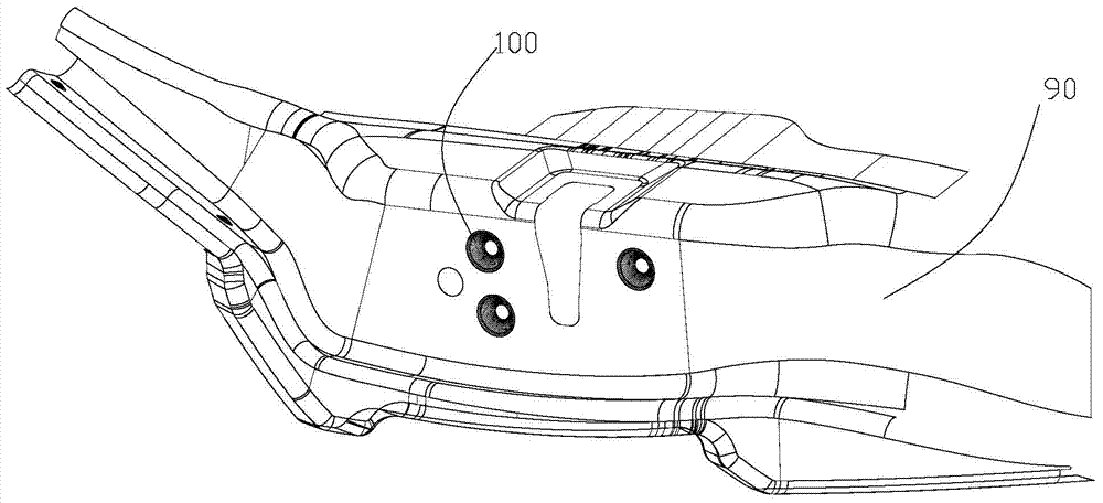
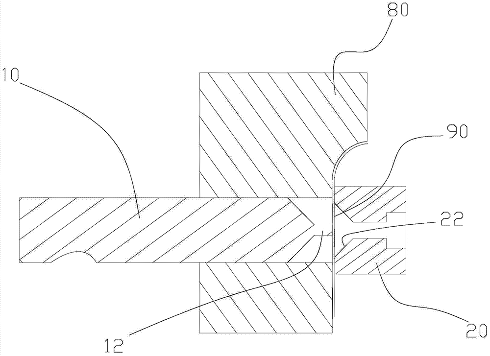
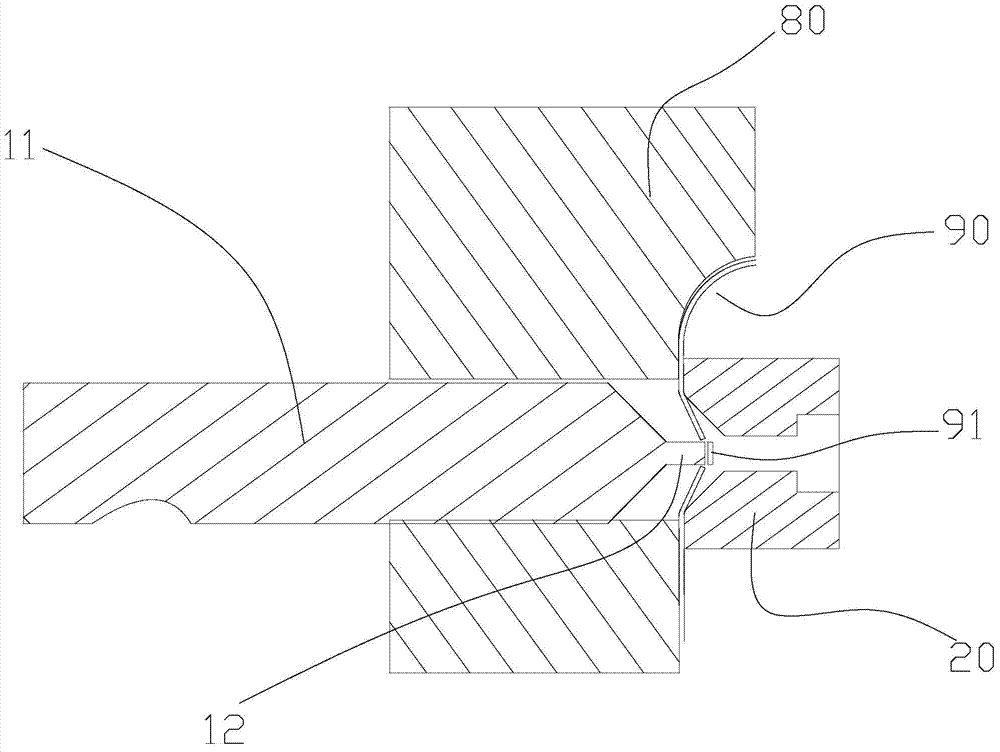
[0055] Such as Figure 7 As shown, a mounting hole punching device of the present invention includes a punch 10 , a die button 20 , a movable block 30 and an elastic member 40 . Wherein, the punch 10 includes a punch rod 11 and a punching head 12, the punch rod 11 is used for connecting with a power source so that the punch head 10 shown can move, and the punch head 12 is used for punching the plate 90 punching. Figure 8 yes Figure 7 The assembly schematic diagram of the mounting hole punching device shown is also a schematic diagram of the working state of the mounting hole punching device. Such as Figure 8 As shown, the mold button 20 is in conflict with the plate 90 , so that the mold button 20 is matched with the punch 10 to punch out the installation hole 100 on the plate 90 . Stamping here includes punching and flanging. Such as Figure 8 In the working state shown, the movable block 30 is arranged in the mold button 20 and the front end is in conflict with the ...


PUM


Abstract

The invention provides an installing hole punching device. The installing hole punching device comprises a punching head, a model button, a movable block and an elastic piece. The punching head comprises a punching rod and a punching hole head, the model button is matched with the punching head to punch an installing hole in a plate, the movable block is arranged in the model button and the front end of the movable block is used for abutting against the plate. The movable block is provided with a channel extending in the moving direction of the punching head, and the shape of the channel is matched with the shape of the punching hole head; when the punching head punches the hole, one part of the punching hole head stretches in the channel; the elastic piece is connected with the movable block; when flanging of the punching head is conducted, the movable block moves along the punching head and enables the elastic piece to be compressed; when the elastic piece extends, the elastic piece drives the movable block to abut against the plate. The installing hole punching device is provided with the movable block, so that when the punching head punches the hole, one part of the punching hole head stretches into the channel extending in the moving direction of the punching head, and then the punching head rushes waste materials directly in the channel. Due to the fact that the movable block is arranged, the occurrence of damage of structures of dies such as the punching head and the model button and plate scrap caused by the fact that the waste materials are reversed on a plastic surface when the punching head punches the hole is effectively avoided.

Description

technical field [0001] The invention relates to the technical field of punching dies, in particular to a mounting hole punching device. Background technique [0002] Such as figure 1 As shown, the mounting hole 100 of the door lock is a tapered recessed hole. Such as Figure 2-Figure 4 As shown, in the prior art, when making the mounting hole 100 of the car door lock, in order to save the process, a wedge-shaped punch 10 is generally used to punch and flang the plate 90 at the same time. Since the mold button 20 does not provide sufficient fit to the plate 90 during punching, the following problems often occur during the punching process: [0003] 1. The mounting hole 100 formed after punching is prone to burrs and tears, and the shape of the mounting hole 100 has a wavy outline, and the accuracy of the mounting hole 100 cannot be guaranteed. Considering the extension of the sheet material 90 and the low factor of the debugging punching speed, the broken waste material 9...

Claims


Application Information

Patent Timeline
Patent Type & Authority Applications(China)
IPC IPC(8): B21D35/00B21D37/10
Inventor 谭植文邓劲松蔡孝魏宪波冯擎峰
Owner ZHEJIANG GEELY HLDG GRP CO LTD
Why Eureka
Try Eureka